14. Present oneself a souvenir – a mini magnetic stirrer

Magnetic stirrer

Magnetic stirrer is very helpful when the stirring area is packed with instruments like pH electrodes, conductivity probes etc which makes stirring by glass rod unable to work. Magnetic stirrer is also necessary for chemical reactions which require long period of stirring. A lot of magnetic stirrers are equipped with hot plates (Fig. 354) as solubilties of most solutes increase with increase of temperature.


(Fig. 354) Magnetic stirrer with heater

14.1 Build a mini magnetic stirrer

A portable and small magnetic stirrer (Fig. 355) not only facilitates laboratory student science experiments but is also useful as a laboratory technician personal instrument for class practical preparations. It enjoys advantages such as small and compact, portal, no venue and time limitation, battery operated (Fig. 356) or AC operated for prolong performance (Fig. 357).  Stirring drinks or other solutions at home are equally suitable. It offers as a souvenir for completing the program.

(Fig. 355)

(Fig. 356)

(Fig. 357)

(i)  Working principle

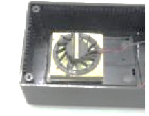
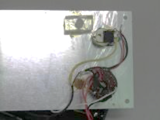
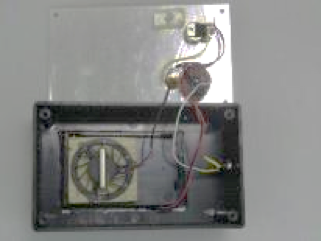
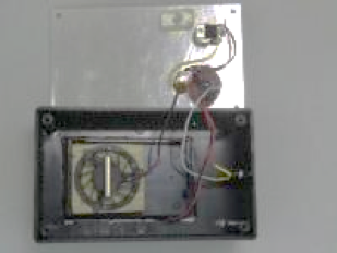
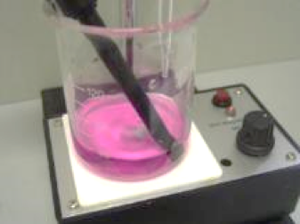
Power of a magnetic stirrer is due to two rotating magnets. One of them is fixed onto a small motor which cannot be seen, and the other is placed in a beaker or other container placed slightly above the magnet / motor combination. Rotation of the magnet / motor combination will cause the above magnet to rotate as well, achieving stirring function. This upper magnet is called a “stirrer bar”. Building this piece of instrument needs basic electronic techniques (Topic 8.1 to 8.3). Soldering skill is also assumed. In case you are not able to recognize electronic components, a simple way to overcome this problem is to write down all the components required and hand the note to the sale person of the supply shop.

(ii)  Material

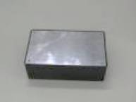
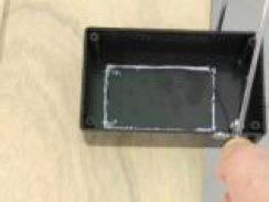
*  A utility box for the case of the instrument (Fig. 358)

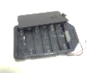
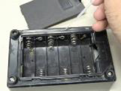
*  A 9V (AA alkaline battery x 6) battery holder with cover (Fig. 359)

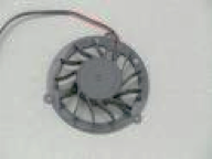
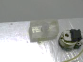
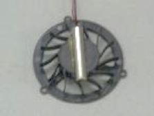
*  A small 5V computer cooling fan (Fig. 360)

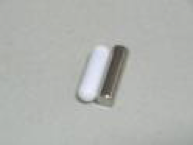
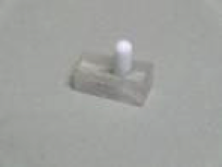
*  A (white) stirrer bar and a strong cylindrical magnet (Fig. 361)

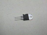
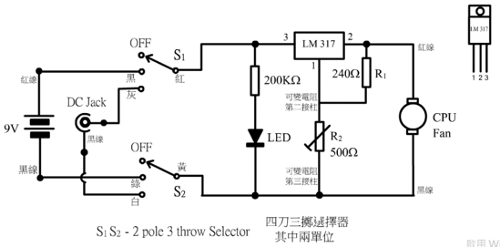
*  Voltage regulator IC LM 317 (Fig. 362), 1/4W 240 Ω and 200 KΩ  carbon resistor

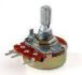
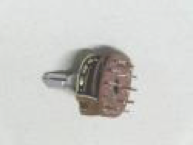
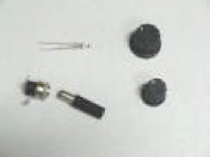
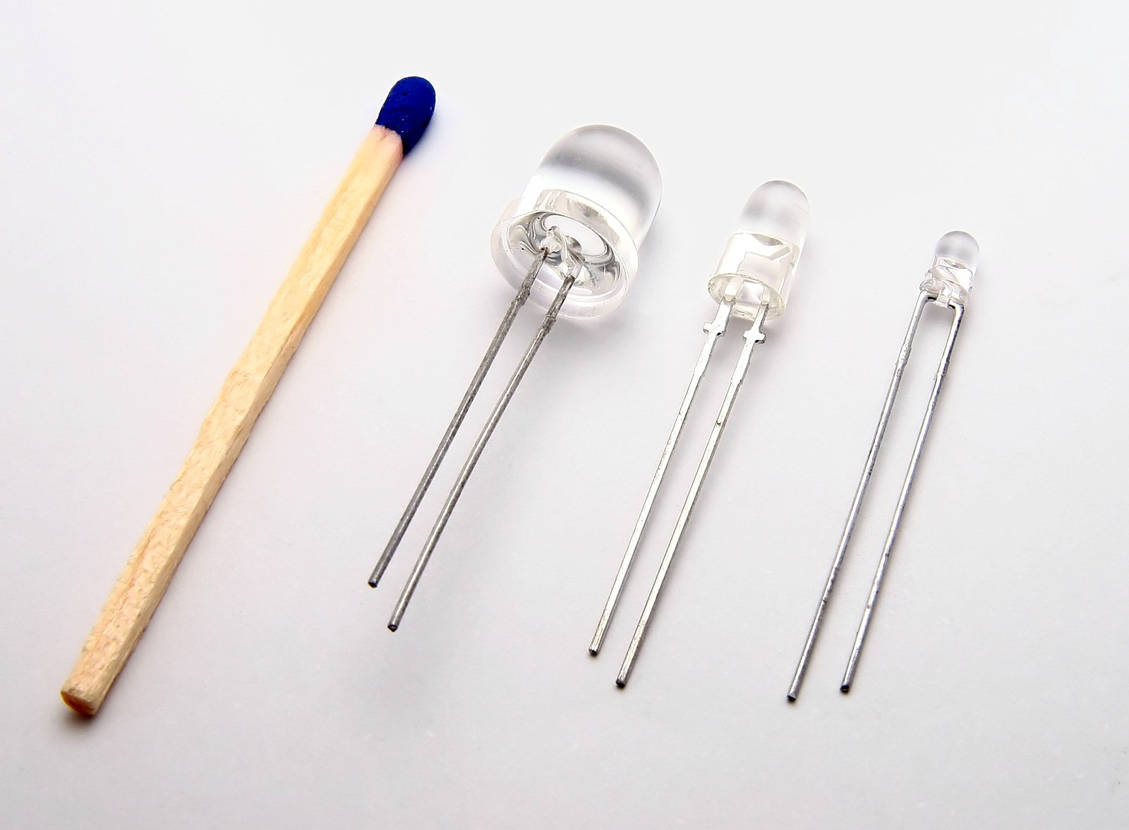
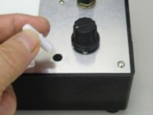
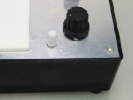
*  500 Ω variable resistor (Fig. 363), 2P3T selector (Fig. 364), 3 mm super bright green LED, small and large knob, 2.1mm DC plug and socket (Fig. 365), connecting wire, rubber leg

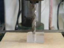
*  Home for the stirrer bar (Fig. 366)

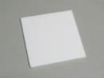
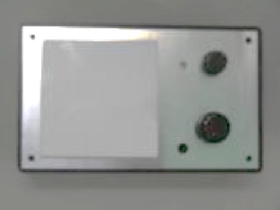
*  A piece of white acrylic sheet for containing the area of stirring (Fig. 367)

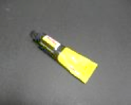
*  Strong adhesive (Fig. 368)

*  Trichloromethane, disposable plastic syringe

(Fig. 358)

(Fig. 359)

(Fig. 360)

(Fig. 361)

(Fig. 362)

(Fig. 363)

(Fig. 364)

(Fig. 365)

(Fig. 366)

(Fig. 367)

(Fig. 368)

Symbol of round light emitting diode LED:


(Fig. 369) Size of LED compared with a match

Available round LEDs are mostly of the superbright type. Instrumental LEDs are provided with one short and one long pin. The long one should be connected to a positive DC supply, while the short one to the corresponding negative power supply. A 3V DC supply will enable LEDs to emit near monochromatic red, yellow, orange, green, and blue lights. White light LEDs are equally popular. LEDs do not work with AC current. Voltage supply of LEDs should not be more than 3V, otherwise they would be permanently damaged.

(iii)  Panel construction

Place the 3 mm superbright green round LED panel light, 2P3T selector, 500 W variable

resistor and the home for stirrer bar into position of various pre-drilled holes. Glue the white acrylic sheet onto the left side of the panel by strong adhesive. Home for the stirrer bar is made as follows: Select a piece of acrylic bar measuring 24 mm (length) x 15 mm (width) x 11 mm (height) dill a hole the size and depth of which just accommodate half the length of the stirrer bar (Fig. 370). Glue it to the bottom part of the panel. Use hand to unplug the protruded part of the resting stirrer part (Fig. 371, 372 and 373).

(Fig. 370)

(Fig. 371)

(Fig. 372)

(Fig. 373)

(Fig. 374)

Glue other parts and install knobs of the variable resistor and 2T3P selector. Half-finished panel is shown in Fig. 374.

(vi)  Construction of the base of the instrument

 For this part, a 9V battery holder, a 5V small computer cooling fan and a DC socket are to be installed.

First use a line saw to cut out a rectangular hole the size of which can just accommodate the 9V battery holder (Fig. 375).

(Fig. 375)

(Fig. 376)

(Fig. 377)

After placing the battery holder, repeatedly use trichloromethane to cement the rim to the base of the instrument (Fig. 376).  Finally glue 4 small rubber legs to four corners for support (Fig. 377).

(v)  Motor/strong magnetic bar combination

Exactly glue the strong cylindrical magnet onto the centre of the top of the cooling fan (Fig. 378). Slight deviation from central positioning can result in severe irregular rotation. Cement the combination to a wooden base. Position of the rotation combination and the wooden base should be just below the cover of the instrument for effective spinning of the stirrer bar. After adjustment, the whole part is glued to the base of the instrument (Fig. 379). One important point is to ensure the spinning mechanism is placed right under the centre of the white acrylic sheet.

(Fig. 378)

(Fig. 379)

(vi)  Soldering of components and circuit

A simple IR circuit for controlling rotation of an electric motor is illustrated by the following diagram (Fig. 380):

According to the formula V= iR,current through the rheostat (variable resistor) connected  in series and the motor are the same and V = i(r + R). By adjusting the rheostat, decreasing r will increase i and hence the speed of rotation. However, unlike linear movement, rotation requires another kind of force – torque, hence it demands extra amount of current. Increase of i increases the p.d. across the motor. However, the rate of increase of this p.d., which contributes positively to rotation, does not match the rate of decrease of r, as the rheostat taps p.d. from the same voltage source. The actual situation can be depicted as follows: At the start, the rheostat has maximum resistance and the motor is stationary. Slightly decreasing the rheostat’s resistance cannot start rotating the motor because the small current increase is not capable of overcoming the torque required to start rotation. At a certain resistance, the motor suddenly starts to rotate rapidly and the actual control is to increase the resistance of the rheostat to decrease the speed of rotation. Also, it is found not possible to decrease the speed of rotation to a few turns before finally stops to move.

In short, variation of the resistance of rheostat is usually not in pace with the variation of current needed for speed change of the motor. In other words, decrease or increase of rotation is not synchronized with change of resistance of the rheostat. Lowering of resistance would not receive immediate speeding up and increasing resistance would not have the expected deceleration effect either.

The method used is summarized below:

(Fig. 380) IR circuit controlling motor speed

Keeping voltage supply constant, vary current by a rheostat to attain speed change according to Ohm’s law V = IR

The method is far from satisfactory. Other method should be used for controlling current and the necessary torque of rotation.

Two commonly used methods:

(i) Adjustable regulated voltage or (ii) Pulse-width modulation

The second method is better than the first one. Pulse-width modulation enables periodic voltage supply, keeping both current and voltage constant. Duration of time of supplying current and voltage controls change of torque moment and affects variation of speed of rotation. Circuits for such method are more complicated. The first one is very simple and suits our purpose of using simple design.

The method of adjustable regulated voltage is summarized as follows:

Vary but regulate the supply voltage. As R of the motor is a constant, change in V will change i and hence the speed of rotation according to the formula of V = iR. Evenly change of i and V will result in evenly change of rotation.

(Fig. 381) Symbolic diagram of the method of adjustable regulated supply voltage

(Fig. 382) Circuit diagram of mini magnetic stirrer

As shown in the above symbolic diagram, all we need is just a regulated but adjustable voltage.

The circuit used for the design is shown in Fig. 382. A 2T3P selector is used to select 2 kinds of input supplies, namely (i) 9V dry cell and (ii) AC 12V voltage adapter (the DC jack). Adjustable regulator IC used is LM 317, a very popular chip for the purpose. Like all regulators, input supply voltage should be higher than the regulated voltage. You don’t have to understand the working principle of the IC. Revise Topic 8.3.3 Applications of voltage regulators for details.

Alter the speed of rotation of the motor need to change the supply current. According to the formula V = iR, where R is the resistance of the motor which is a constant,increase of V will increase current and hence the speed of rotation. The regulated voltage output of LM 317 varies from 1.25V to [1.25 x ]V. Circuit design assigned R1 to be a 240 Ω resistor and R2 to be a 500 Ω variable resistor. This means the output voltage varies from 1.25V to [1.25 x ]V, or 3.9V. This range of voltage variation is just good for the motor to start from stationary to attaining a maximum speed of rotation. The motor used is a small computer cooling fan which consumes very little current, typically in the order of 10 mA. Powered by dry cells, the stirrer can maintain continuous spinning for a day or more.

A few components are required and there is no need to use universal circuit board. Simply solder the parts together. Handle the LM 317, 500 Ω variable resistor, 2T3P selector, 1/4 W 240 Ω and 200 KΩ resistor as shown in Fig. 383.

(Fig. 383)

(Fig. 384)

Secure the soldered combination onto the aluminium panel. Connect the 9V battery holder leads, the soldered combination, 1/4W  200 KΩ resistor, panel LED, small motor, 2P3T selector and the DC jack with connecting wires (Fig. 384).

Finished assembly:

Front view

(Fig. 385) 

Interior view

(Fig. 386) 

Home of the stirrer bar

(Fig. 387) 

Instrument in operation

(Fig. 388) 

14.2 Applications of the mini magnetic stirrer

 *  For low solubility solutes which need long periods of stirring for solvation, like sodium oxalate or copper (II) sulphate.

*  To accommodate other instrumental probes during stirring like pH measurement in titration experiment (Fig. 389).

*  For stirring in special kind of equipment, like volumetric flask.

*  Stirring for solution while performing other experiment.

*  As a personal instrument for laboratory technicians.

(Fig. 389) 

14.3 Maintenance

The instrument is housed with a stirrer bar. It can be used with no time and venue limitations. It works conveniently with bench top equipped with 12V DC/AC low voltage supplies. The whole circuit consumes approximately 80 mA current and 6 AA alkaline batteries enable the instrument to spin continuously for tens of hours. Annual renewal of batteries is adequate. Use rechargeable batteries is even better. Basically no need for monitoring its performance. In case there is problem, just uncover the panel and look for detached parts or joints that become loose.