3.  Traditional and innovative micro-scale school-level general chemistry instruments

General school chemistry instruments like test tube and beaker are used for heating / observing colour of substances /chemical reactions etc. Likewise, distillation apparatus can separate solute or solvent from solutions. All school chemistry instruments are simple and traditional, most of them had hundred years of existence. Traditional equipment can be purchased easily and there is no need to homemade them.

Micro-scale instruments for school chemistry experiments that are not purchasable have to be homemade. A few points worth noting:

*  Plastics should be the first choice of construction material. It is light, easily formed, easily available and inexpensive, especially good for utility box selection. Cannot withstand heating and not suitable for containing organic solvents.

*  The phrase “School-level micro-scale chemical reactions” has no specific definition. Normally, using one tenth of conventional amount of reagents are considered as micro-scale chemical reactions.

*  Safety precaution is the first priority. For example: It is much safer if harmful gases like SO2, Cl2 and NH3 can be handled in a contained manner allowing no leakage of reacting gases. Details of this design will be described in Topic 3.2 “Reaction Disc”.

*  Try to look for domestic or consumer items as ready-for-use instrument or components of design, like disposable syringe for volume measurement or plastic medicine bottle for parts of colorimeter construction (Topic 5.3).

*  Higher price for better quality means cost effectiveness. Like using more costly silicone tubing instead of less expensive rubber tubing renders nicer appearance and longer lifetime.

*  Take the initiative in spare time to shop around by going to hardware stores or electronic component shops for creative idea inspiration. Canton Rd. or Reclamation St. of Mongkok or Apliu St. of Shamshuipo are hot spots for hanging around.

Commercial chemistry micro-scale instruments are usually purchasable in the form of kits assembled in a box. Availability as such may not be suitable for all experiments required for a specific syllabus. To make it simple, you use only one item set from the box that you bring to the lab. This works if no lab is available. However, if resources are adequate, all experiments, irrespective of traditional or micro-scale, should be performed in a lab. Instrument designed for Program (2) is targeted at a particular DSE experimental technique. This way solved the above problem.

3.1 Micro-scale Water-less Distillation Set and suggested experiments (1) and (2)

DSE Syllabus Topic I “Planet Earth”, Topic V “Fossil Fuels and Carbon Compounds” and Topic XI “Chemistry of Carbon Compounds” all require students to understand the principle, to practice the technique and to appreciate the applications of distillation. Unlike traditional distillation apparatus (Fig. 10), the introduced design of micro-scale distillation set involves creative idea, innovative skill and more importantly, the inspiration of environmental conservation oriented “Green Awareness”.

Introduction

Performing group-based small scale organic distillation experiments in school laboratories often encounter the problem of inadequate sets and poor experimental yield. All-glass “Quick-fit” distillation apparatus does not help much, because if micro-scale amount of reactant is used and after passing the condensation passage, the resulting yield of distillate is usually zero. Commercial micro-scale kits usually use plastic materials. They cannot withstand heating and are incapable of handling organic substances, let alone reflux or distillation.

The problem can be solved by using the following method: (i) use traditional test tube for reaction, (ii) do not use water for condensation purpose, use a special “coolant” (Fig. 3) purchasable from super-markets to act as strong cooling agent instead, (iii) make a small device to act as a “cold finger”, (iv) make a special small distillate cup to collect “nascent” distillate, (v) use a pin-shaped digital thermometer to register temperature and (vi) make a mini homemade low voltage heater to cater for naked-flame free heating. The program includes two experiments specifically designed for water-less micro-scale reflux and distillation as an alternative of traditional distillation by water condensation. Experimental results showed much higher efficiency and reliability.

“Micro-scale Water-less Distillation Set”

Code

Description

1

Mini-heater

2

“Distillate Cup”

3

“Cold Ring”

4

Small test tube

5

Silicone teat

6

Pasteur pipette

7

Digital thermometer “Summit 310”

8

“Cold Stick”

 (A)  Construction of the “Cold Stick” 

Running water used as condensation coolant in traditional distillation is dumped into the sink and wasted. Such practice is really not environmental. A simple solution is not using water as coolant.  A special reusable coolant pack (Fig. 4) to keep food chilled during picnic time is readily available from supermarkets. Simply put it cool in a freezer overnight and you will get a powerful cooling device like a big ice. The chemical used inside the plastic pack is a strong organic cooling agent which is very safe and unharmful. It is an ideal coolant for condensation in place of water.“Cold Stick” consists of a brass rod and a transparent plastic tube containing the strong coolant as mentioned earlier (Fig. 5). It works like a “cold finger”. Position of copper or brass in the electrochemical series is below hydrogen. Metallic copper has substantial strength of resistance to simple organic reaction corrosion. As such, we found “Cold Stick” is safe for handling simple organic substances like alkanols, esters, haloalkanes or alkanoic acids. Unlike university level organic chemistry practical, only limited simple organic reactions requiring distillation like preparations of esters and haloalkanes are included in senior secondary school chemistry experiments and that makes the design suitable for use at school level.

(Fig. 4) Coolant pack

(Fig. 5) Completed “Cold Stick”

First prepare a 100 mm (high) x 35 mm (diameter) transparent acrylic tube. Two amber acrylic 5 mm thick disc with the same diameter dimension as the transparent tube. Each amber disc has one central pre-drilled 8 mm diameter hole, one disc has one small hole for liquid coolant injection. Carefully and repeatedly cement the amber disc onto the two ends of the transparent tube with drops of trichloromethane from a disposable syringe (Fig. 6 and 7), revise Program (1) Topic 5 Materials and Forming). Insert the brass rod into the two holes of the discs and cement both ends with epoxy glue. Using a 50 cm3 plastic syringe and by inserting into the small hole of one of the amber discs, fill the cavity of the tube 8/10 full with the liquid coolant. Finally seal the small hole with epoxy glue. Finished “Cold stick” is shown in Fig. 8 and 9.

 (Fig. 6)

 (Fig. 7)

 (Fig. 8)

(B)  Construction of the “Distillate Cup”

Traditional condensation (Fig. 10) uses a water condenser to cool the vapour to form distillate. The vapour has to travel a certain distance before the distillate drops to the collector and this situation becomes crucial to micro-scale distillation. As the initial mass of reactants are small, the final yield could be very limited or even no distillate would be collected. Targeting this problem, a straight forward solution is to collect the “nascent” distillate where it is formed. A special homemade “Distillate Cup” (Fig. 21) when capped to the end of the brass rod (Fig. 9 and 11) can receive all the initial distillate right after the reaction starts. The nascent distillate collected by the “Distillate Cup” is 100% pure,

Prepare the following materials:

1.A section of 10 cm long 8 mm diameter brass rod (L)
2.A section of 8 mm long 8 mm internal diameter brass tube (L1)
3.A section of 10 mm long external diameter 11 mm internal diameter 8.4 mm brass tube (L2)
4.A brass or copper disc 8 mm diameter 0.2 mm thick with a central hole of diameter 0.8 mm
5.A copper sheet measuring 29 mm long, 15 mm wide and 0.1 mm thick.
6.A small 0.2 mm thick copper sheet
7.A section of 25 mm long thick connecting wire
8.A small working platform

Wrap the 0.1 mm thick copper sheet round the brass rod (L) one turn, forming a cylindrical wrap (Fig. 12). Insert L2 (just fit, Fig. 13). Place the brass disc over one end of the cylindrical wrap (Fig. 14). Clamp the combination and place it on a small working platform (Fig. 15). Solder two suitable points (one is the junction between the disc and the copper wrap and the other is just the opposite, Fig. 16). Remove the brass rod from the wrap/disc combination. Finally close the copper wrap with another solder joint. The completed cap (Fig. 17) is just good for capping the brass rod. Solder the thick connecting wire onto the wrap/disc combination to form another part as shown in Fig. 18.

Place L1 over the 0.2 mm thick small copper sheet. Apply solder and trim spare parts (Fig. 19) to form a small cup as shown in Fig. 20. Make a small hole at the centre of the cup, allowing the connecting wire to go through.

 (Fig.9)

 (Fig.10)

 (Fig. 11)

 (Fig12)

 (Fig.13)

 (Fig. 14)

 (Fig.15)

 (Fig.16)

 (Fig. 17)

 (Fig.18)

 (Fig.19)

 (Fig. 20)

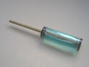
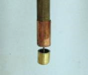
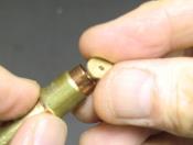
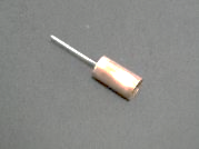
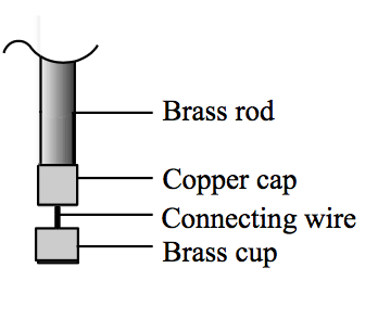
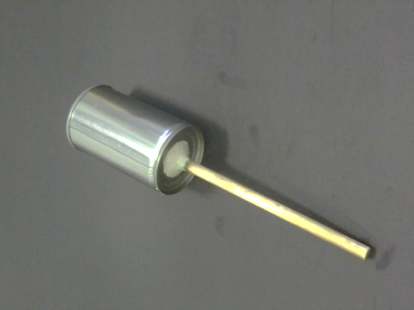
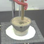
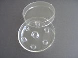
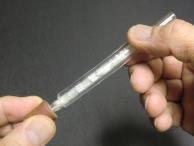
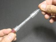
 Finally solder and trim the cap and the cup together to form a “Distillate Cup” (Fig. 21).


(Fig. 21) Finished “Distillate Cup”

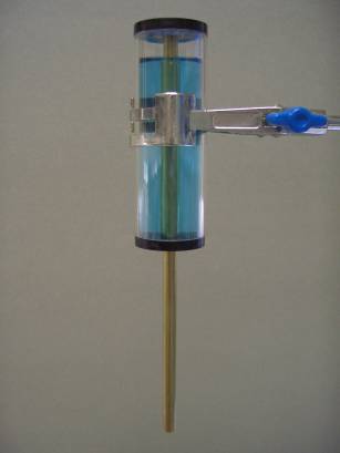
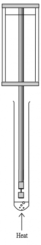
Schematic diagrams of the Micro-scale Water-less Distillation Set:

Cold Sick: a transparent plastic cylinder 8/10 filled with a strong liquid coolant. A central brass rod acts as a “cold finger”. Can be reused by placing in a freezer.

Distillate Cup: Formed by a small cap connected to a small cup. The cap end is to be capped onto the brass rod while the cup end receives distillate.

Water-less micro-scale distillation setup

(C)  Construction of the “Cold Ring”

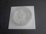
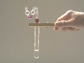
“Cold Ring” (Fig. 22) is used for cooling while taking the boiling point of the distillate. It provides a cooling surface for refluxing the distillate. Usually, time taken for measurement is short and this device is optional. Moist with cold water a small piece of 15 mm thick circular sponge with a central hole which fits a small test tube. It is placed near the mouth of the small test tube.

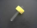
(Fig.22) “cold Ring” for cooling

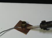
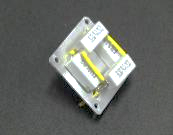
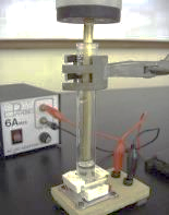
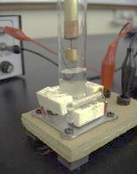
(D)  Construction of the “Mini Low Voltage Heater”

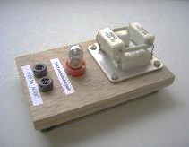
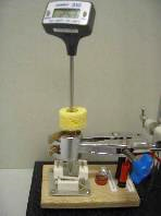
(Fig.23) Mini low voltage heater

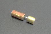
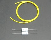
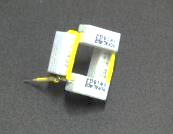
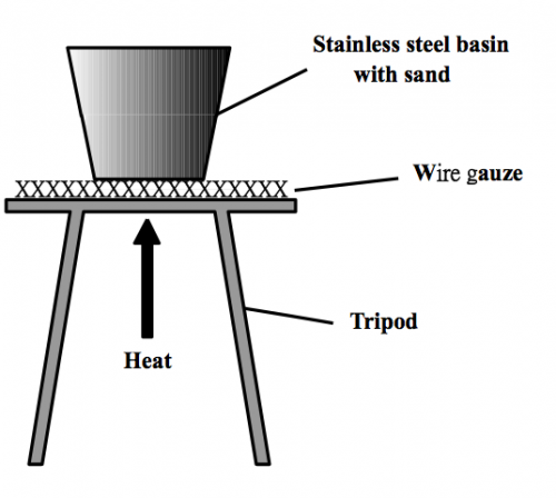
Organic liquids are flammable and should not be heated by naked Bunsen flame. Using electric heater is one way and using a hot sand bath is another. Commonly available cement resistors are suitable to act as small electrical heaters (Fig. 24). Four 5W 18W cement resistors connected in parallel to form a shape of 井 (Fig. 25) can function as a 20W heater, the central hollow part accommodates a test tube nicely.

All joints have to be soldered permanently. Sections of Teflon tubing (yellow tubing of Fig. 24) or ceramic tubing are used for heat insulation of exposed linings, as all parts will become very hot upon passage of current for some time. Normal solder has melting points above 200C and the cement resistor combination can attain a maximum temperature around 150C, after considering environmental cooling factors.


(Fig. 24)

(Fig. 25)


(Fig. 26)

Cement the 井like heater combination onto an aluminium sheet by strong metallic epoxy glue for heat dissipation (Fig. 26). Fix the entire combination onto a wooden plate. Assemble a pilot lamp for illumination (Fig. 27). Start heating by applying a low voltage (12V) AC or DC current (3A). The device could supply heating power for test tube distillation for at least half an hour (Fig. 28).

(Fig. 27) Finished mini-heater

(Fig. 28) Setup for micro-scale distillation

(E)  Pin-shaped digital thermometer

(Fig. 29) “Summit 310” pin-shaped thermometer


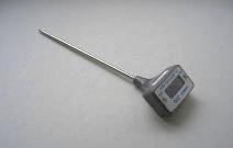
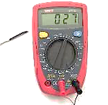
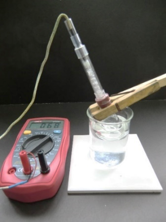
(Fig. 30) DMM with miniature thermocouple for temperature measurement (at 27 degree C)

The Set uses a pin-shaped digital thermometer (“Summit 310”, Fig. 29) for measuring boiling points of distillate. The thermometer has a resolution of ± 0.1oC and can be placed into a small test tube. Alternatively, the thermocouple as an accessory of a DMM can also be used. However, the latter can display only integer numbers (Fig. 30).

(i) Reflux, (ii) Distillation and (iii) Checking boiling points of distillate:


(Fig. 31) Reflux

(Fig. 32) Distillation

(Fig. 33) Boiling point determination

Experiment (1): Preparation of 2-chloro-2-methylpropane (page 76)

Experiment (2): Preparation of ethyl methanoate (page 78)

Postscript:

The idea of using “Cold Stick” is creative, but the design is a bit fancy. If aimed at getting the result and not care much about appearance, the design can be simplified to just using an opened tin with a hole at the bottom and attaches to a brass rod. Brass rod is a very good conductor of heat and is not suitable for large area soldering. (A+B) type metallic epoxy cement binds the rod and the tin hole nicely. Cooling agent is a handful of small ice cubes or simply cold water (Fig. 34, 35).

Mini heater is also a fancy design. It could be completely do away with by using traditional sand bath (Fig. 36, 37) which does not use electricity or provide naked flame.

Micro-scale preparation of tert. butyl chloride

(Fig.34) Drill a central hole at the bottom of the tin, allowing a brass rod to go through. Fix by (A+B) metallic epoxy cement.

(Fig. 35) Add small ice cubes

(Fig. 36) A stainless steel cup containing sand pre-heated to around 300oC

(Fig. 37) Setup for reflux/distillation

3.2 “Reaction Disc” and suggested Experiments (3), (4) and (5) 

In order to avoid inhaling poisonous gases like SO2, Cl2, or NH3, school experiments involving these gases usually use their aqueous solutions instead. However, if use the micro-scale technique and contain the gases so that they are not allowed to leak out, gaseous reactions can still be performed. “Reaction Disc” was designed to solve the above problem. Another advantage of using the device is that it allows 6 experiments to be performed at the same time, this greatly shortens the time for experimentation. Program Topic IV “Acids and Bases” and Topic VII “Redox reactions, Chemical Cells and Electrolysis” include some of the chemical reactions of the concerned aqueous ions. “Reactions Disc” provides a vivid display of reaction results with the parent gases. For example, change in pH values by the presence of SO2 and NH3, the various oxidation or reduction results in the presence of Cl2 or SO2 and the formation of precipitate by NH3.

Instrument construction and operation

“Reaction Disc”(Fig. 38) consists of a transparent plastic disc, the centre of which is glued with a big well, six other smaller wells are also glued symmetrically round the periphery. Basically, it is a micro-scale gas generator with testing facility, very suitable for school chemistry experiments.

Cut two transparent acrylic tubes with different diameters to obtain sections of separate lengths of 9 mm and 7 mm to act as big and small wells. Cut separately a 2 mm thick 70 mm diameter transparent acrylic disc to act as base. With the help of a disposable syringe or a micro-tip plastic pipette, cement the wells onto the disc with trichloromethane as shown in Fig. 39 and 40. The finished combination can be nicely placed into a 75 mm diameter Petri-dish (Fig. 41).

To operate: Place reagents that will generate gas into the big central well and testing reagents for the generated gas into the peripheral small wells. Immediately place the prepared disc into a Peri-dish and cover it with the lid. Place the entire setup over a white background, a piece of paper or tile will do (Fig. 42). Generated gas will diffuse slowly to all parts of the covered Petri-dish without any leakage. Results of the chemical reaction at each small well can be observed after a couple of minutes. A magnifying lens for clearer observation is a good idea. Alternatively, using a light table (Fig. 43) for observation is also great.

(Fig. 38)

(Fig. 39)

(Fig. 40)

(Fig. 41)

(Fig. 42)

(Fig. 43)

Experiment (3): Redox and acidic properties of sulphur dioxide gas (page 82)

Experiment (4): Redox, acidic and bleaching properties of chlorine gas (page 84) 

Experiment (5): Redox, alkaline and precipitation properties of ammonia gas (page 86), (Extension: complex ion formation)

3.3 “Micro-scale Fractionating Column” and suggested Experiment (6)

Tradtional fractional distillation  

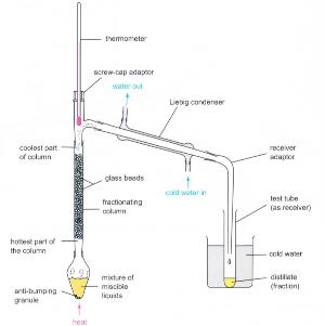
(Fig. 44) Traditional fractional distillation setup

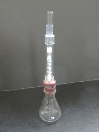
 (Fig. 45) Micro-scale fractional distillation

The design is a miniature type of traditional setup.

Construction main points:

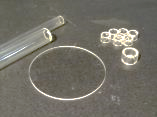
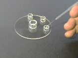
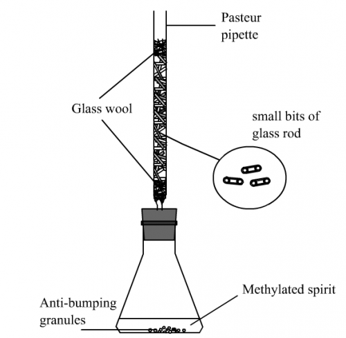
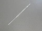
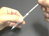
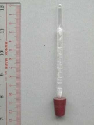
(i)   Pasteur pipette glass tube to act as fractionating column body (Fig. 46).

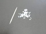
(ii)  Mini glass tubing available from knitting accessory material shops in Shamshuipo (Fig. 47) to act as condensation/evaporation elements inside the column.

(Fig. 46)

(Fig. 47)

(Fig. 48)

(iii)  Remove the tip of the Pasteur pipette by a using a file. Insert some glass wool to the end of the prepared small column (Fig. 48). Carefully fill the column with the mini glass tubings to a height of 60 mm, place another patch of glass wool to hold the inserted mini glass tubings and to complete the column for fractionating function. The tip of the combination is fitted with a rubber stopper while the body is enclosed by a 70 mm long transparent plastic tube with a diameter of 10 mm (Fig. 49) for providing heat insulation as a large amount of heat could be lost to the environment making the temperature of the top of the column unable to reach component boiling points. Finally, transparent heat-shrinkable plastic tubing is used to seal both ends of the column, leaving the top part of the column for temperature measurement (Fig. 50). Dimension of the fractionating column and setup is illustrated in Fig. 51 and 52.

(Fig. 49)

(Fig. 50)

(Fig. 51)

(Fig. 52)

(Fig. 53)

(Fig. 54)

For operation, just connect the finished micro fractionating column to a small 10 cm3 conical flask (Fig. 52). The top of the instrument cannot accommodate an alcohol-in-glass thermometer. A pin-type digital thermometer or the miniature thermocouple probe of a DMM (Fig. 53) has to be used. It is very educational for students to observe the repeating condensation/evaporation cycles taking place inside the column while performing the experiment (Fig. 54).

Note:10 cm3conical flask is not readily available. A small test tube with boiling chips is actually a better alternative as it is less vulnerable to sudden boiling of liquid.

Experiment (6): Fractional distillation of wood spirit (page 89), (Extension expt.)

3.4 “S-Tube” and suggested Experiments (7) and (8)

School chemistry experiment for testing a gas usually use a delivery tube (Fig. 55). After observation, if the setup is removed from the heating source for cooling, “sucking back” phenomenon will occur due to a decrease in pressure inside the hot test tube upon cooling the hot moisture to liquid water, the testing reagent will be sucked back to the hot test tube. A hazardous situation in which cracking of the hot test tube may occur.

(Fig. 55)

(Fig. 56)

(Fig. 57)

S Tube Introduction

“S-Tube” Testing gases

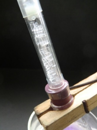
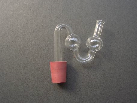
“S-Tube” is a section of glass tube with two small bulbs bent in the form of letter “S” (Fig. 56). The small U-shaped section is for placing a few drops of testing reagent (Fig. 57). One of the bulb functions as a container for the testing reagent when the released gas formed from the reaction pushes it outwards while the other bulb acts as another container for the retreating testing reagent when “sucking back” occurs. Thus, the testing reagent remains staying at the U-shaped junction between the two bulbs, even though it is forced to experience rough pushing and pulling. “Sucking back” will not occur during heating operation.

 Experiment (7): Properties of carbon dioxide gas (page 94)

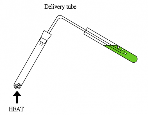
Place a few drops of lime water into the U-shaped part of the “S-Tube”. Fit the prepared “S-Tube” to a test tube containing reagents that release CO2 gas upon heating. The lime water will turn milky. Some lime water will get into the outer bulb but will not come out. On cooling, some lime water will get into the inner bulb but again will not come out. Hence a “S-Tube” is better choice than a delivery tube. In addition, the small amount of testing reagent used (a few drops) means the experiment is environmentally friendly.

Experiment (8): Properties of sulphur dioxide gas (page 96)

3.5 “Electrolysis Stick” and suggested Experiments (9) and (10)

“Electrolysis Stick” (Fig. 58) is a simple device with two electrodes which can be directly capped onto a 9V battery. To use: press the combination against a strip of filter paper wetted with electrolyte and indicator.

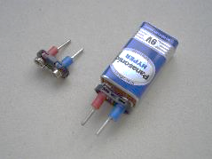
(Fig. 58) “Electrolysis Stick”

Experiment (9): Migration of ions and electrolysis of dil. NaCl with addition of universal indicator by “Electrolysis stick” (page 97)


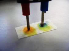
(Fig. 59) Colour developed at the anode and cathode

Experiment (10):  Migration of ions and electrolysis of dil. KI by “Electrolysis stick” (page 99)

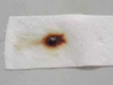
(Fig. 60) Colour developed at the anode: dark brown due to I3 , I2 at the centre

3.6 “Flour Explosion Kit” and suggested demonstration

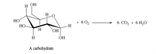
In 2015, an outdoor “color powder party” was held in a water park in Taipei, Taiwan. A devastating dust fire occurred, resulting in heavy casualties. The substance which caused the explosion was corn starch powder. Had the stage operators known the combustion between air and carbohydrate (corn starch powder) increases rapidly with increase in surface area of carbohydrate in powder form, they would have aware of the imminent large-scale devastating explosion. Unfortunately, the lesson was not learnt and in 2018 a similar smaller scale dust explosion occurred during a birthday celebration party at the Baptist University of Hong Kong. In fact, numerous huge barn explosions often occurred worldwide, all bear the same reason.

(i)  Objective of demonstration

To demonstrate the relationship between rate of oxidation reaction and surface area of reactant.

(ii)  Theory

Reaction rate increases with increase in surface area of reactants. Unlike factors of concentration and temperature, factor of particle size cannot be quantified, or expressed by equations with variables. The relationship between rate and particle size is empirical, it can even follow an exponential curve. Combustion is rapid oxidation with oxygen (air). A stick of spaghetti (a kind of carbohydrate) will slowly burn in air. However, if it is grinded into powder, combustion will become very vigorous and generates flashing flames. If the whole scenario is confined to a closed can with a lid, the pressure generated by combustion is more than enough to blast off the lid like a flying cannon with stunning loud sound.

ΔHcomb = – 4759 kJ mol-1

(iii)  Steps of demonstration

(1)    Ignite a stick of spaghetti with a gas lighter. Note the rate of burning in air.

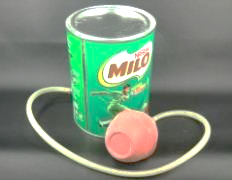
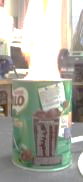
(2)  Place about 50 g flour in a “Milo” can (Fig. 61), with the powder slightly covering the nozzle as shown in the diagram below:

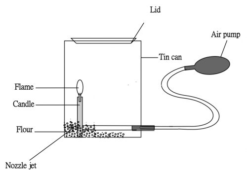
Ignite a candle. With the can open without the lid, squeeze the hand pump and see if a throwing flame can be detected. Repeat the procedure a number of times by adjusting the candle position to ensure achieving a very vigorous flame (Fig. 62). Quickly close the can with the lid until you hear a “Click” sound. Press the air pump immediately and be prepared for a stunning explosion with the lid shooting out like a cannon, to the room ceiling!

Points to note:

*  No need to cover the nozzle with flour. Let the compressed air from the hand pump form an air jet and cause the nearby powder to form a flour mist. This way gives better results.

*  Put some lubricant like WD 40 over the rim of the lid for decent lifting without much force, otherwise a tight lid will become a bulging lid upon heat expansion and cannot let go of.

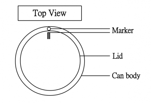
(3)  Extent of lid shooting depends on the tightness between the lid and the can. This again depends on (i) tightness between the lid and the rim of the can (controllable) and (ii) whether the lid is always closed at the same position. We should not assume that the lid can evenly cover the at any position irrespective of trial, like a glass plunger of a glass syringe can always fit any barrel of the same size. However, we can overcome this problem by a simple trick, as shown by the diagram below, which is self-explanatory:

(4)  Let the lid cool after the demo, repeat if necessary (or upon students’ request!).

(5)  With some on-the-site experience, an average teacher should achieve an 80% success rate, the sound may not be too overwhelming though. Continue trying!

(Fig. 61) Setup

(Fig. 62) Furious flashing flame

Flour dust explosion

The small-scale explosion caused by this dust explosion kit is absolutely safe. It is similar to the common school experiment “pop sound” test for hydrogen gas. Hydrogen gas mixed with air is highly explosive and can cause devastating destruction. Recall the 1936 Hindenburg airship disaster. However, the “pop sound” test for hydrogen gas is very safe, though they are of the same kind of explosive nature.