Traditional non-electronic quantitative equipment usually include burette, pipette, measuring cylinder, syringe, stopwatch etc. Quite a number of micro-scale chemistry experimental kits are available commercially. Quantitative parts of these kits usually include plastic micro burette, micro electrolysis device or well plates for chemical reactions. Choice of parts for a specific syllabus is limited. Hence there is a need to design micro-scale quantitative instruments required for a specific syllabus.
4.1 8-well reaction strip and suggested Experiments (11) and (12)
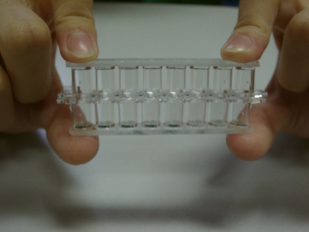
Use of flat-bottom transparent 8-well plastic strip (Fig. 63) for micro-scale chemistry experiments was not a new design. It had been widely used in North American high schools for decades, not a mainstream adoption though. It has a special feature of having the ability of keeping the contained aqueous liquid not falling when turned upside down, as a result of sufficient surface tension established between the well wall and the liquid (Fig. 64). Bigger well strips (e.g. 9-well strip) do not possess this special feature.
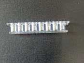
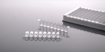
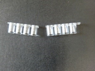
Flat-bottom transparent 8-well plastic strips and assembled well plates are common equipment for clinical laboratories (Fig. 65). Today, purchasable 8-well plastic strips are not tough (although it was) and can be easily broken (Fig. 66). They are not suitable for practical use by dexterity-immature school students. A simple solution to the problem is to glue the bottom part of the 8-well strip onto a clear acrylic strip with trichloromethane (Fig. 67). This makes the 8-well strip sturdy and not vulnerable to breaking
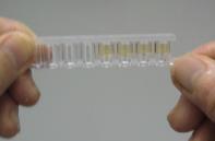 | ||
| (Fig. 63) Flat-bottom transparent 8-well plastic strip | (Fig. 64) With care, even if the strip is turned upside down, contained liquid will not fall down | (Fig. 65) A number of 8-well strips assembled to form a 96-well plate |
 | |
| (Fig. 66) Strip easily broken | (Fig. 67) Apply a drop of trichloro-methane to the junction between the well and the additional strip by using a syringe |
8-well strip has a special usage in micro-scale chemistry experiments.
A formal chemistry rate experiment usually requires undergoing a number of individual experiments with varying variables and record the finishing times. Four individual experiments can render a decent quantitative study. The time taken is simply the total time for all four experiments.
The “shake-down” technique based on the special feature of an 8-well reaction strip as mentioned below allows a number of experiments to be performed at the same time. This saves a lot of time and also serves as time-gain for repeated trials for the sake of gaining accuracy.
Method employed is as follows: Place 9 small drops of one reactant with varying concentration into each of the small well by using a micro-tip plastic pipette. Call it “A” strip. Prepare “B” strip with another reactant. Carefully invert strip “A”, place it precisely over strip “B”. Hold the combination with two hands and give it a sudden and powerful downward shake. Contents of strip “A” will collapse into strip “B”. Flip the combination and repeat the procedure at least twice to ensure complete mixing of both reactants for reaction. This technique is called “shake-down” (Fig. 68).
(Fig. 68) “Shake-down” technique
DSE Syllabus Topic IX “Rate of Reaction” and Topic XIII “Industrial Chemistry” list factors affecting reaction rate like concentration or temperature. 8-well reaction strip offers an innovative micro-scale method of investigating the kinetic order of a reaction.
Using the “shake-down” technique, the quantitative relationship between concentration and reaction rate of a reaction can be completely solved unexpectedly fast. Following this, the rate equation of the reaction can then be established. Micro-scale approach plus a mere two minutes of completion of an experiment are irresistible advantages.
The main reaction of the “iodine clock reaction” (Experiment 11 for details) is the redox reaction between acidified H2O2 (aq) and I- (aq), according to the following equation:
![]()
Variation of rate of reaction and concentration bear proportionality relationships. Degree of variation is not only confined to qualitatively high or low, Numerical quantitative variation is much more scientific. Often, an equation can be established in which reaction rate can be calculated by substituting suitable variables.
The rate equation for the main reaction of the “iodine clock reaction” is:
![]()
Where k is the rate constant. The reaction is said to be first order w.r.t. I-(aq) and H2O2(aq) and zero order w.r.t. H+(aq). Total kinetic order is two. Using a micro-scale innovative design of 8-well reaction strip and based on the “1 2 4 8” technique (Experiment 11 for details), the kinetic order w.r.t. each reactant of the “iodine clock reaction” can be nicely and speedily determined.
Please note:
Quantity of reactants used affects accuracy of experimental results. Small amount of reactant gives less obvious result. Also, using number of drop as volume variable as opposed to actual volume measurement is less precise as volume of individual drops are hardly the same. All these attributes to greater experimental error using micro-scale approach compared with traditional methods. A straight forward solution is to repeat the micro-scale experiment a number of times and average the reliable results.
Experiment (11) Micro-scale kinetic order of acidic oxidation of iodide ion by hydrogen peroxide – “Iodine clock reaction” (page 100
Experiment (12) Micro-scale quantitative analysis of reaction rate of acidification of sodium thiosulphate – the “Disappearing cross Experiment” (page 108)
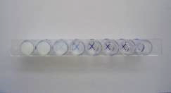
(Fig. 69) “Disappearing cross” Experiment
4.2 “Mini Heater” for quick determination of activation energy of “iodine clock reaction” and suggested Experiment (13)
Quantifying reaction rate or establishing a rate equation basically relates rate variation with variation in concentration and temperature of reactants. Topic 4.1 depicts the quantitative variation in concentration with rate by determining the kinetic order of the reaction. The equation is given by rate = k[I(aq)-][H2O2(aq)], which does not take into account the factor of temperature variation. The constant k (called as rate constant or looked upon as the rate for unit concentrations of reactants) is in fact only a constant at a fixed temperature, it varies with increase or decrease of temperature. The mathematical relationship between k and temperature T is given by the Arrhenius equation which states:
k = Ae ![]()
where ΔHact is called the activation energy. The smaller the value of ΔHact, the faster will be the reaction rate (note that ΔHact is a negative value). A and R (the gas constant) are general constants. The logarithmic form of the Arrhenius equation is expressed as
ln(k) = ln(A) –![]()
constant k is in fact the rate for unit concentrations of reactants. Thus, it is inversely proportional to time t or 1/t. Following this, ln (k) will be proportional to ln (1/t). The above equation can be expressed as
ln(1/t) = ln(A) –![]()
A graph of ln (1/t) vs (1/T) will give a straight line with a slop of – ΔHact/R. Knowing the value of the slope, ΔHact can be calculated.
Gathered from Topic 4.1 and 4.2,we can establish a complete rate equation of the “iodine clock reaction” as:
Rate = (Ae![]() )([I-(aq)][H2O2(aq)])
)([I-(aq)][H2O2(aq)])
Instrument Construction
Using naked flame or simple water bath are the common methods of heating aqueous solutions. The above methods are not able to achieve a pre-determined temperature accurately. The ideal method is to heat the solution slowly and repeatedly, which is exactly how a water bath with thermostat works. The designed mini heater uses the same principle of heating, but employs eyeing plus a manual ON/OFF switch in place of an automatic thermostat to heat a heater to attain a precise temperature. A simple circuit to illustrate the idea is shown in Fig. 70.
 (Fig. 70) Mini heater circuit
Composition of the instrument: Two small heater probe (Fig. 72) and an instrument panel (Fig. 71). A low voltage supply of 12 V DC is required. AC voltage also works but the illumination LED will be blind.
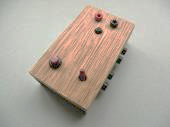 |  |  |
(Fig. 71) | (Fig. 72) | (Fig. 73) |
1. Mini electric heater probe
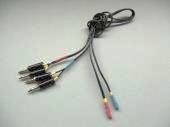
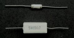
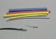
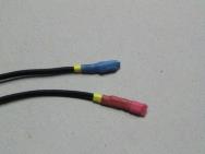
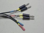
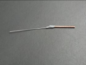
Take out the embedded wire resistor of a 15 W 5W cement resistor by hammering (Fig. 74). Bent one lead of the wire resistor and solder it onto a cable wire, with the other lead insulated from the first lead. Fix the combination with layers of heat shrinkable plastic tubing so that the probe end is completely sealed, water-proof and insulated from the surrounding (Fig. 75, 76). A finished pair of heater probes with colour distinction (red and blue) for quick setting is fitted with banana plugs (Fig. 77).
Note: Do not pass current for heating unless the probe end is completely immersed in the aqueous solution. Otherwise, the wire resistor of the probe will be overheated and damaged.
(Fig. 74) | (Fig. 75) | (Fig. 76) | (Fig. 77) |
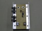
2. Control panel
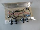
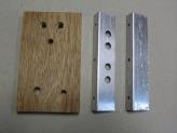
Basically, the control panel consists of a wooden plate with pre-drilled holes of various sizes and two pieces of angle aluminium sections, also with pre-drilled holes (Fig. 78, 79). List of components:
Item description | Qty |
| 5 mm yellow LED with mount as panel light | 1 |
| Banana socket (black) | 4 |
| 1P2T toggle switch | 1 |
| Push ON switch | 1 |
| 2A fuse with mount | 1 |
| 5 kW 1/8W carbon film resistor | 1 |
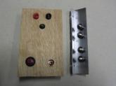
Assemble and fix all components onto the wooden plate. Attach each of the angle aluminium sections to two sides of the wooden plate with screws (Fig. 80). Connect the leads of all components as laid out in the circuit of Fig. 70 with solder as shown in Fig. 73.
(Fig. 78) | (Fig. 79) | (Fig. 80) |
3. Instrument operation
Again note: Pass current only when the probes are completely immersed in the testing solution.
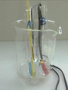
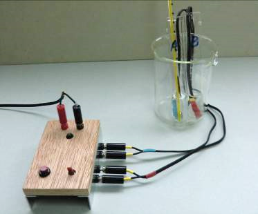
First connect the instrument to a low voltage supply, follow by the red (A) and blue (B) probes. Place probe A into a boiling tube containing solution A. Probe B is also placed into another similar boiling tube containing the same amount of solution B. Place a thermometer into one of the boiling tubes. A beaker is used to contain the two boiling tubes which serves as a heat insulator from the surroundings (Fig. 81). The whole setup is shown in Fig. 82. The first step of passing current is to switch on the 1P2T toggle switch. Wait till the temperature of both boiling tubes reach slightly below the required temperature, switch off the 1P2T toggle switch. Press repeatedly the press ON switch until the temperature of both boiling tubes reach exactly the required experimental temperature. Mix the two solutions by pouring for reaction to take place. Start taking time when half of one of the solutions is transferred. Refer to Experiment (13) for details.
| (Fig. 81) | (Fig. 82) |
Experiment (13) Determination of the activation energy of the iodine clock reaction (page 112)
4.3 “RMM Kit” and suggested Experiment (14)
Instrument Description
DSE Syllabus Topic IX “Rate of Reaction” mentioned the determination and calculation of Molar volume of gas constant at r.t.p. (24 dm3).
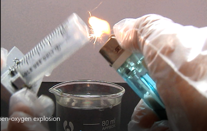
Micro-scale RMM Kit (Fig. 83) is a simple but innovative device for quick determination of the relative molecular mass of butane gas at room temperature and pressure conditions. Alternatively, it can be used to derive the Molar Volume Constant of 24 dm3 at r.t.p. by assuming a value for the RMM of butane gas.
An experimental error of less than 5% agrees with slight deviation from literature value. Higher accuracy can be achieved with electronic balances of 0.001 g resolution.
The set can be used for student experiment or projected by using a visualizer as real time demonstration.
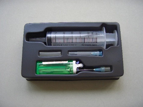
(Fig. 83) “Micro-scale RMM Kit”
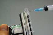
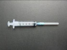
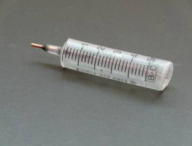
| RMM Kit consists of: | 1. a 60 cm3 capacity plastic disposable syringe, 2. a butane gas cigarette lighter fitted with a hypodermic needle for gas discharge, 3. a spare hypodermic needle and 4. a section of silicone rubber tubing placed on a vacuum-formed plastic tray. |
 |  |  |
(Fig. 84) | (Fig. 85) | (Fig. 86) |
Operation of the Kit is simple and straight forward.
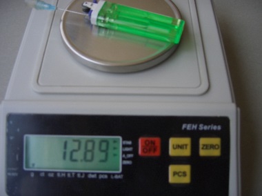
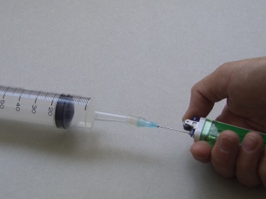
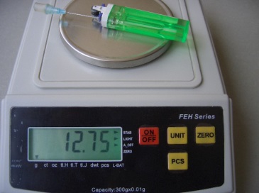
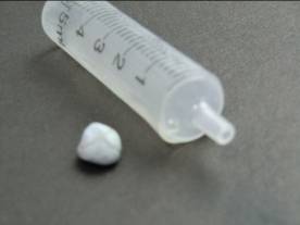
| Procedures: | 1. The butane gas lighter fitted with a hypodermic needle is weighed with an accuracy of at least ± 0.01 g (Fig. 84). 2. Butane gas is released into the 60 cm3 capacity plastic disposable syringe until a volume of 60 cm3 of butane gas is collected (Fig. 85). 3. The discharged butane gas lighter fitted with a hypodermic needle is weighed again (Fig. 86). 4. Assuming a Molar Volume Constant of 24 dm3, a value for the relative molecular mass of butane gas based on the mass and volume of gas collected at r.t.p. is calculated. |
Results and calculation
Initial mass of butane gas cigarette lighter = 12.89 g
Final mass of butane gas cigarette lighter = 12.75 g
Mass of butane gas released = 0.14 g
Volume of butane gas collected = 60 cm3
Relative molecular mass of butane gas = [0.14 x ] = 56 g mol-1
(Literature value: RMM of C4H10 = 58 g mol-1)
Percentage experimental error = = 3.4%
Remarks
The hypodermic needle is cemented onto the nozzle of the lighter by ‘Super Glue’. Butane gas cigarette lighters are available from all supermarkets. Choose those that fit the vacuum-formed plastic tray. The plastic tray is for storage only, it is dispensable.
Experiment (14) Micro-scale determination of the Gas Constant (R) at r.t.p. (page 118)
Releasing butane gas
4.4 “Electrolysis tube” and suggested Experiment (15)
The topic of electrolysis of water is included in secondary school science or chemistry syllabuses worldwide. The concept to be delivered is that water can be decomposed by DC current to form hydrogen gas and oxygen gas. Ratio of volume of hydrogen gas to oxygen gas released is 2:1. Equation of electrolysis of water is expressed as follows:
![]()
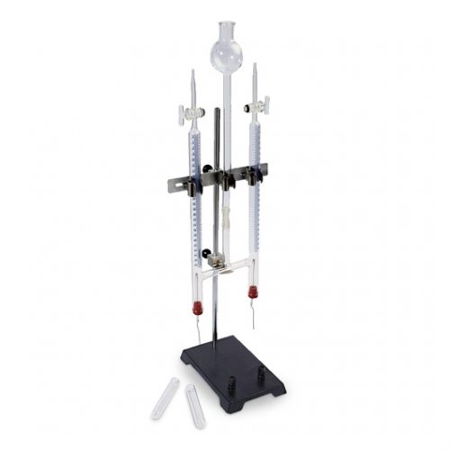
Traditionally, a Hoffmann apparatus (Fig. 87, 88) is used for qualitative and quantitative electrolysis experiment. Released oxygen gas can re-light a glowing splint while the hydrogen gas gives the “Pop” sound test.
| (Fig. 87) Hoffmann apparatus | (Fig. 88) Schematic diagram |
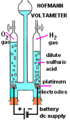
Hoffmann apparatus uses expensive platinum plate as electrodes. It is good for class demonstrations. For student experiments, much less expensible graphite electrodes (dismantled from used dry cells) are used instead. Graphite electrodes, however, are prompt to easy breakage and corrosion by the oxygen gas released.
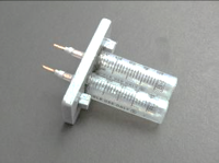
“Electrolysis Tube” (Fig. 89) employs nichrome wire instead of graphite rod as electrodes. The main advantage in using nichrome wire is that it is resistant to air oxidation (nichrome wire when heated to red hot returns to its previous condition when cooled to room temperation with no signs of corrosion or oxidation) and sturdy. Its drawbacks include only good for dil. NaOH as electrolyte while others may have chemical reaction and it is also vulnerable to halogen oxidation. School chemistry syllabus focuses more on the aspect of chemical decomposition of water into hydrogen and oxygen and their volume ratio. Discharge of ions other than H+(aq) and OH‑(aq) can be illustrated by redox displacement reactions according to the electrochemcial series instead of undergoing electrolysis. Choice of using dil. NaOH as electrolyte for electrolysis meets this condition because only H2 and O2 gases are evolved. Thus, “Electrolysis Tube” is very suitable for the DSE Chemistry Syllabus Topic VII. The setup can be easily converted to a simple H2/O2 fuel cell is an added advantage.
(Fig. 89) “Electrolysis tube”
Instrument construction and operation
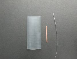
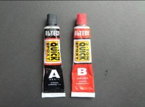
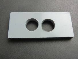
(1) Prepare the following materials: (i) Two 5 cm3 disposable plastic syringe (Fig. 90), (ii) clear heat-shrinkable plastic tubing, (iii) SWG 16 bare copper wire, (iv) nichrome wire (Fig. 91), (v) (A+B) metallic epoxy glue (Fig. 92), (vi) a 8 mm thick PVC strip with two 15 mm diameter holes (Fig. 93).
(2) Saw away the top part of the syringe, cover the barrel part with clear heat- shrinkable plastic tubing by using a hot soldering iron (Fig. 94). Punch a small hole in the top part of the plastic syringe. It serves as a valve for gas release to attain atmospheric pressure inside the barrel. A bit of “Blu Tack” is used as an ON/OFF stopper for the hole (Fig. 95).
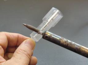
(3) Nichrome wire and copper lead cannot be soldered. Direct contact is the only means of joining them. It is done as follows: select a section of heat-shrinkable plastic tubing the size of which slightly over-fits the copper lead, hoop it firmly and permanently with the nichrome wire electrode. Finally seal the contact portion with metallic epoxy glue (Fig. 96). The combination forms an electrolysis electrode.
(4) Thread the prepared electrode through the nozzle of the plastic syringe and seal the arrangement with metallic epoxy glue. (Fig. 98). The barrel/electrode combination acts as a chamber for gas collection. After finishing this step, a unit of a pair of electrodes designed for gas collection has been constructed.
(Fig. 90) | (Fig. 91) | (Fig. 92) | (Fig. 93) |
(Fig. 94) | (Fig. 95) | (Fig. 96) | (Fig. 97) |
(5) A pair of prepared (electrode + chamber) is inserted into the double-hole PVC strip and again fixed by metallic epoxy glue (Fig. Two small stops can be glued to the bottom of the set for adjusting position. The setup is ready for electrolysis.
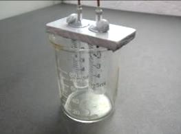
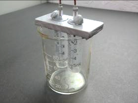
(6) Rest the setup on a 100 cm3 beaker (Fig. 99).
Commencing experiment
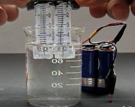
(1) Place about 80 cm3 0.5M NaOH into a 100 cm3 beaker. Seal the two small openings of the syringe by two bits of “Blu Tack”. Raise the finished combination a bit to see that the two liquid columns inside the syringes do not fall down. This ensures there is no leakage of air inside the air chamber of the syringes (Fig. 100).
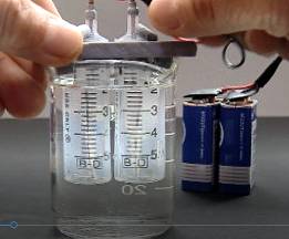
(2) Connect the setup to a portable low DC voltage and start electrolysis (Fig. 101).
Electrolysis
(Fig. 98) | (Fig. 99) | (Fig. 100) | (Fig. 101) |
Performing various tests
(a) Hydrogen to oxygen volume ratio (details refer to Expt. 15)
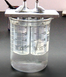
(Fig. 102) hydrogen to oxygen volume ratio of 2:1
1 : 2 Volume ratio of H2 to O2
(b) Measurement of e.m.f. of a simple fuel cell formed by the generated hydrogen and oxygen gas in the presence of alkaline medium (details refer to Expt. 15).
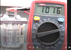
(Fig. 103) Initial e.m.f. of alkaline hydrogen/oxygen fuel cell
Measurement of e.m.f. of the generated alkaline fuel cell
(c) “Pop” sound test for hydrogen gas (Refer to Expt. 15)
(Fig. 104) “Pop” sound test
“Pop” sound test”
(d) Glowing splint test for oxygen gas (details refer to Expt. 15)
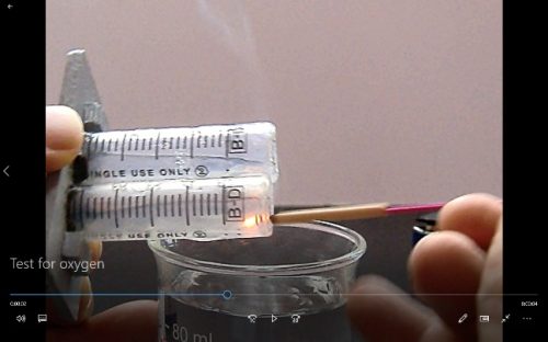
(Fig. 105) Test for oxygen gas
Test for oxygen gas
Experiment (15) Qualitative and quantitative analysis of electrolysis of water by using the “Electrolysis Tube” (page 122)12
4.5 “Micro-scale Heat of Combustion Kit” and suggested Experiment (16)
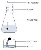
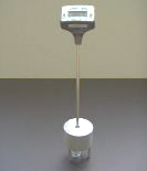
(Fig.106) Traditional setup for the determination of heat of combustion
Traditional setup for determination of heat of combustion
The above diagram shows a traditional school level chemistry experimental setup for the determination of heat of combustion (or enthalpy change of combustion) of ethanol. By determining the mass of ethanol burnt and the increase of temperature of water, a value of DHcomb can be calculated by applying the formula DH = ms (DT). Unfortunately, experimental result deviates a lot from the literature value, mainly because of the heat loss to the surrounding during experiment.
Using the method of heating liquid water is not the only way, heating solid substance like aluminium block is even more convenient. The micro heat determination kit employs “dual experiment calibration” technique to eliminate heat loss to the surrounding (details refer to Experiment 16).
 |  |
| (Fig. 107) | (Fig. 108) |
Enthalpy of combustion means the heat energy released when one mole of a combustible substance is completely burnt. Combustion of petrol (hydrocarbons) forces car engines to work. Combustion of carbohydrates, e.g. the mechanism of (digestion + absorption + oxygenation) provides energy for human beings. The conventional method of determination of enthalpy of combustion is actually burning the substance to release heat which causes the temperature of another substance to increase, quantified experimental data collected is used for calculation.
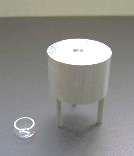
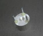
Micro-scale Heat of Combustion Kit comprises of (i) a small glass bowl to contain the combustible substance, (ii) a cylindrical aluminium block with stand and (iii) a thermometer (Fig. 107 and 108).
Construction of the aluminium block with stand
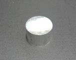
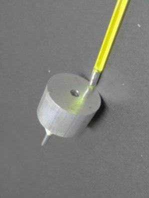
Cut a section of solid cylindrical aluminium rod with a dimension of (i) 26 mm (length) and (ii) 38 mm (diameter) (Fig. 109). At the centre. drill a hole of diameter 6.2 mm hole of depth just good to fit a thermometer (Fig. 110). Near the periphery and at equal distance, drill three separate holes each of diameter 3.8 mm to hold 30 mm long aluminium rods taken from 6.2 x 13 mm blind rivet nails. Make a 15 mm circular pit at the centre of this face to increase surface area for flame heating.
Insert the three small aluminium rods into the three peripheral holes, allowing 20 mm for protrusion and seal them permanently with metallic epoxy glue. This serves as three legs for stabilization (Fig. 111).
|
|  |
(Fig. 109) | (Fig. 110) | (Fig. 111) |
Experiment 16: Determination of the Standard enthalpy change of combustion of propan-1-ol (page 128)
Meltometer (熔度計)
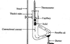
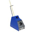
Meltometer kit (Fig. 114, 115) is an innovative design for the determination of melting point of solid compounds. Unlike the Thiele tube which uses paraffin oil (Fig. 112) or electrical melting point apparatus (Fig. 113), it simply uses Bunsen flame. A heat contained layer of air formed by a small and a big test tube is used to heat the melting point tube indirectly by a Bunsen flame. The device can determine a range of melting points, depending on the thermometer used. Meltometer achieves quicker heating and cooling rate than other melting point apparatuses.
 |  |  |
| (Fig. 112) | (Fig. 113) | (Fig. 114) Meltometer |
(Fig. 115) | (Fig. 116) | (Fig. 117) | (Fig. 118) |

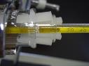
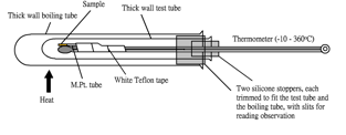
| Meltometer kit consists of: | 1. a thick-wall test tube, 2. a thick-wall boiling tube, 3. a mercury-in-glass thermometer (-10 – 360o C) 4. Two silicone stoppers, each trimmed with a slit for temperature reading observation, one fits the test tube and the other, actually a stopper with much of the interior hollowed out, looking like a ring, fits the boiling tube, 5. a roll of white Teflon tape (for pipe repair, M.Pt. over 400o C), 6. a magnifying glass and 7. a small test tube containing 10 pcs of melting point tube. |
Operation of Meltometer is as follows:
1. Wear safety spectacles
2. Place small amount of dry powdered solid sample into the melting point tube
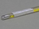
3. Cut a section of Teflon tape and use it to wrap up the melting point tube and the thermometer, leaving the mercury bulb to face the heating environment (Fig. 118)
4. Fit the melting point tube/thermometer combination with the small silicone stopper and insert the whole assembly into the test tube
5. Cover the test tube with the bigger silicone stopper/ring and place the whole setup into the boiling tube
6. Adjust the position of the two silicone stoppers so that temperature readings can be read and exchange of air between the boiling tube, the test tube and the atmosphere can be maintained (Fig. 117)
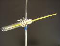
7. Slightly tilt the setup with an iron stand and clamp (Fig. 116)
8. Strongly heat the bottom part of the setup with a hot Bunsen flame
9. Use the magnifying glass to observe the state of the sample
10. Stop heating when the temperature is close to the melting point of the sample (temperature of the hot insulated layer of air will keep rising steadily)
11. Record the temperature reading when the sample changes from oblique to clear
12. Dismantle the hot setup and let it cool well below the recorded temperature
13. Repeat the experiment at least once for reliable result
Note: After finishing the experiment, allow enough time for the hot apparatus to cool to room temperature before returning the kit to storage.