AM analogue signal transmission associates with lots of noise or interference. They are not suitable for long distance distortion-free transmission. During the 70s of last century, invention of using near infra-red laser beam as carrier wave and special optical fibre cable, succeeded in transmitting 50Mbit/s ASK (Amplitude-Shift-Keying) signal up to a distance of 10 Km. This endeavor opened the door to rapid growth of digital optical fibre communication. Digital transmission is much more superior than copper cable analogue transmission. Also, the “Father of optical fibre” was the renowned Nobel Prize winner Prof. Kuen Kao (高錕博士) of Hong Kong.
Bandwidth and broadband
(a) Bandwidth of landline analogue signals
Bandwidth of landline analogue AM signals is the wavelength of carrier wave or called as “frequency range”. Frequency of sound wave is expressed as cycles/s or Hz. The range of frequencies necessary for an analogue voice signal, with a fixed telephone line quality (recognizable speaking), is 300 – 3400 Hz. This means that a decent choice of bandwidth of voice signal to be propagated is 3,100 Hz. Bandwidth of carrier wave (Fig. 289) should be higher than the voice signal bandwidth (i.e 3,100 KHz) for effective modulation and transmission. In the past, amplitude modulated carrier wave propagates with a few hundred KHz (e.g cable Redifussion of H.K. in the 60s). Landline analogue signals suit telecommunication but not video communication.
Units of analogue signal bandwidth are KHz or MHz.
(b) Bandwidth of digital signals
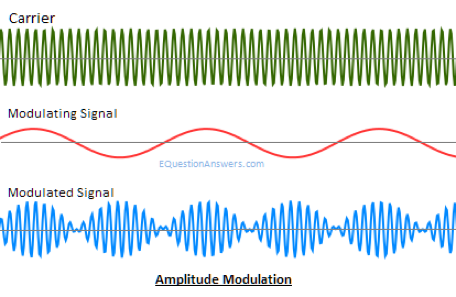
Modulation of (0 1) bit signal and carrier wave generate digital signals suitable for transmission. On the other hand, demodulation is the process of regenerating the (0 1) bit signal from the digital signal. The Modem (Modulation/demodulation) we frequency used in computing devices possesses both of the above functions. Amplitude-Shift-Keying (ASK) (Fig. 290) is the basic modulation method used for digital transmission.
| Digital source signal |  |
| High frequency electromagnetic carrier wave |  |
| Amplitude-Shift-Keying transmission |  |
(Fig.290) ASK (Amplitude-Shift-Keying) transmission
For analogue signal amplitude modulation transmission, transmission volume depends only on voice signal bandwidth. Associated electromagnetic carrier wave serves as transmission medium, somewhat like a dummy. Volume of digital signal transmission concerns the carrier wave as well. Data volume (data word) of digital transmission is determined by the frequency of the carrier wave and the bus width of (0 1) byte in unit time. It is formulated as the product of bus width and the working frequency. For example, for a 64-bit, 800 MHz bus, transmitted data volume = (64 bit) x (800 Mhz) = 51200 Mb/s or 51.2 Gb/s or (51.2/8 GByte/s) = 6.4 GB/s, a very high transmission speed.
Unlike analogue signals, units of digital signal bandwidth involve bits/s and not cycles/s. Currently, less than10Mb/s transmissions are regarded as low or narrow bandwidths while those greater than 10Mb/s transmissions are of high bandwidth or commonly called as “broadband”.
Digital transmission can be accomplished by (i) optical fibre cable or (ii) wireless mobile web network.
A simple analogy between complicated digital data transmission and a down-to-earth example of river transportation using a boat to deliver goods to a destination in a given time is tableted as follows:
| Digital transmission | River transportation | ||
| Bus width: | 16-bit 2 byte | Boat size: | Small |
| Modulation method: | Unsuitable | Packaging of goods: | Ill-organized |
| Carrier wave frequency: | Low | River flow: | Slow |
| Data word: Less byte/s | Volume of goods delivered: small | ||
| Bus width: | 64-bit 8 byte | Boat size: | Large |
| Modulation method: | Suitable | Packaging of goods: | Using containers |
| Carrier wave frequency: | High | River flow: | Rapid |
| Data word: Much more byte/s | Volume of goods delivered: very large | ||
(c) Data transmission and broadband
Digital data transmission is the transfer of data (a digital bit stream or a digitized analog signal) over a point-to-point or point-to-multipoint communication channel. Examples of such channels are copper wires, optical fibers, wireless communication channels, storage media and computer buses.
Definition of the term “broadband” understandably varied over time. It was once considered to be any technology with transmission rates above the fastest speed available over a telephone line, i.e 56 Kb/s. Later, as of 2015, FCC (Federal Communications Commission) of USA defined broadband as any transmission rate of internet download speed of 25 Mb/s and upload speed of 4Mb/s. All in all, “broadband” stands for a high-data-rate connection to the Internet.
(d) Ways of connecting PC to the internet (dial-up method is no longer used):
A desktop personal computer cannot be directly plug into a wall socket for connection to the internet, you have to get help from a commercial telecom company, i.e. an Internet-Service-Provider or ISP (except laptops, netbooks or smartphones using WiFi) which provides access to the internet server. A modem has to be connected between the wall socket and the PC
(i) Using existing telephone twisted pair copper cable and telephone port (Rj11 plug) on the wall
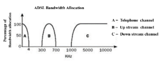
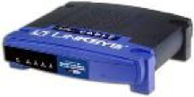
An ADSL (Asymmetric Digital Subscriber line) modem (Fig. 293) is required for a wall telephone port. ADSL technology employs the current copper infrastructure to provide broadband services over existing telephone lines. ADSL uses frequency-division multiplexing (FDM) technique to separate voice and data into a baseband telephone channel, an upstream data channel, and a downstream data channel. Each channel occupies a different portion of the frequency spectrum, as shown in Fig. 292. Using ADSL modem to access the internet would not affect the associated audio communication. ADSL can achieve upstream speeds of up to 1.5 Mbps and downstream speeds of up to 12 Mbps, usually in a 1:10 ratio. ADSL is therefore ideal for providing high-speed Internet access to homes and businesses where download speeds are more critical than upload speeds.
The most common way of connection through telephone line to the broadband internet is by using PPPoE (Point to Point Protocol over Ethernet). It is a kind of manual input requiring the input of IP (Internet Protocol) address, netmask, DNS (Domain Name System) address and the Gateway address (Fig. 291). It delivers voice as well as data signals.


2G(Second Generation)
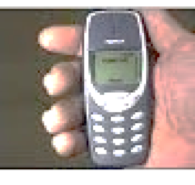
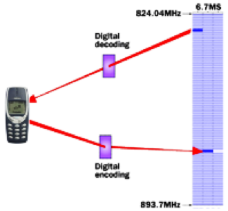
“Cell” handsets were too bulky and clumsy for portability (Fig. 297), let alone the limited transmission range and time of usage because of poor battery power. Soon after the introduction of 1G “cell” handsets, 2G (Second Generation) mobile digital phones were available. The Nokia “Connecting People” series of mobile phones (Fig 298) dominated the market in the late 90s. 2G mobile communication employed encrypted digital voice transmission, more frequent use of the radio-wave spectrum of 900 MHz and data transfer in the form of SMS (Short Message Service) text message, e-mail or small size files.
Technology standard and assessing method of 2G
2G (Second Generation) refers to wireless data transmission download rate up to 0.1 Mbps. The technology standard of 2G was the GSM (Global System for Mobiles) and the main accessing method was the TDMA (Time Division Multiple Access). TDMA is a process of sharing a single radio channel by dividing the channel into time slots that are shared between simultaneous users of the radio channel. Voice calls are transmitted one following the other, using one’s own assigned time slot. For example, a user allocated the 6.7 ms time slot for sending and receiving data is illustrated in Fig. 301. View relevant internet information for details.
 |
 |
| TDMA | CDMA |
|
(Fig. 301) TDMA splits a frequency range into time slots. |
(Fig. 302) In CDMA, each phone’s data has a unique code |
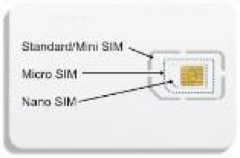
GSM devices needed a SIM card (Fig. 304) for ISP recognition. A subscriber identification module (SIM), widely known as a SIM card, is an integrated circuit that is intended to securely store the international mobile subscriber identity (IMSI) number and its related key, which are used to identify and authenticate subscribers on mobile telephony devices (such as mobile phones and computers). It is also possible to store contact information on many SIM cards. SIM cards are required for GSM phones and CDMA phones, they are also needed for the 4G LTE handsets. SIM cards can also be used in satellite phones, smart watches, computers, or cameras
3G(Third Generation)
3G technology aimed at “people to people”. That means real time voice and interactive data communication.
Unlike 1G and 2G which aimed mainly at providing voice transmission service, Third Generation (3G)mobile communication technology provided extra services such as broadband applications, access to the internet and multimedia functions. 3G (Third Generation) refers to wireless data transmission download rate up to 14 Mbps and upload rate up to 6 Mbps. 3G wireless communication system started the era of high-speed data transmission
Technology standard and assessing method of 3G
Although 3G technology was developed after the 2G GSM accessing method, 3G phones have GSM compatibility. Along with TDMA, 3G transmission technology of CDMA (Code Division Multiple Access) is another example of multiple access, where several transmitters can send information simultaneously over a single communication channel. This allows several users to share a band of frequencies (bandwidth). CDMA employs Direct Sequence Spread Spectrum technology (dsss) and a special coding scheme (in which transmitting data is treated with a scrambling device) (Fig. 302). Only users possessing descrambling devices are able to receive data sent to themselves. CDMA allows more calls, along with data transmission, over the same bandwidth at the same time.
Although 3G CDMA does not need SIM card, 3G W-CDMA (Wideband Code Division Access) phones all go with SIM cards for compatibility with the existing GSM band spectrum.
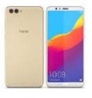
High speed data transfer enabled 3G networks spawned the first generation of handsets which enable domestic video calls. 3G promoted real-time game playing, social media interactive activities (Facebook, Twitter), website browsing, video viewing (Youtube) etc. The popular brand of 3G handsets were the Apple’s iPhones (Fig. 299), followed by Samsung.
WiFi (Trademark of Wi-Fi Alliance)
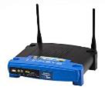
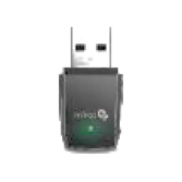
For appliances without SIM cards such as laptop or notebook, WiFi connection is the only means for wireless access to the internet. WiFi was created and maintained by IEEE (Institute of Electrical and Electronics Engineers). The world’s most widely used wireless computer networking standard of 802.11 (Fig. 303) had been adopted extensively for home and office networks, allowing laptops, notebooks, printers and digital cameras to interact with one another and access the Internet without connecting wires. A router (Fig. 305) or a portable Wi-Fi “egg” (Fig. 306) are commonly used. Alternatively, an USB WiFi router (Fig. 307) can also be plugged in for WiFi connection for desktop computers with no cable ethernet.
| Generation/Version | Linkrate range |
| WiFi 6 (802.11ax) | 600-9608 Mbit/s |
| WiFi 5 (802.11ac) | 433-6933 Mbit/s |
| WiFi 4 (802.11n) | 72-600 Mbit/s |
| 802.11g | 3-54 Mbit/s |
| 802.11a | 1.5-54 Mbit/s |
| 802.11b | 1-11 Mbit/s |
(Fig. 303) Versions of Wi-Fi standards


Standard of 5G
2019 was the year for setting a standard for 5G communication. Early 2019 was still figuring out the essential 5G features and functionalities. The primary 5G standards bodies involved in these processes are the 3rd Generation Partnership Project (3GPP), the Internet Engineering Task Force (IETF), and the International Telecommunication Union (ITU). In late 2019, the 3GPP Release 15 standards speculated that early rollouts of 5G networks and devices be brought under NSA (Non-Standalone) 5G operation – meaning 5G networks will be aided by existing 4G infrastructures. Service providers who want to be first to offer 5G speeds will start with NSA. Once 5G coverage is established, standalone (SA) 5G will be implemented according to the 2020 3GPP release 16 standards. The difference between NSA and SA 5G networks is illustrated in Fig. 311. Industrial 5G needs extra low latency (1ms or less) and is assumed by the deployment of SA 5G together with cloud-native and optical fibre broadband 5G Core (5G C), independent of the existing 4G LTE networks.
NSA 5G SA 5G
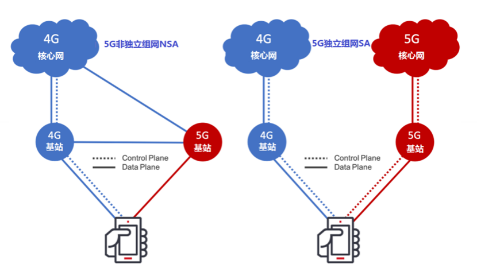
(Fig. 311) Difference between NSA 5G and SA 5G Network
The imminent task of 5G infrastructure seems to be a massive production of optical fibre-based station linkage. Success of 5G coverage is highly dependent on the extent of completeness of terminal optical fibre network. Human technical support is another very important aspect of 5G deployment. Professional electronic technology training providing enough maintaining personnel is crucial. China’s huge domestic plantation of base stations and development of innovative 5G technologies such as smartphones, IoT, wireless remote-controlled medical operations etc, meant China should be an important stake-holder in the universal 5G standard.
As of 2020, NSA would be the prevailing ISP network, because exisisting smartphones are largely 4G handsets. A 4G smartphone cannot make use of 5G networks’ faster data speeds. Perhaps it takes 5 years or so for the market to provide enough 5G handsets and more base stations with optical fibre terminal linkage.
6G(Sixth Generation)
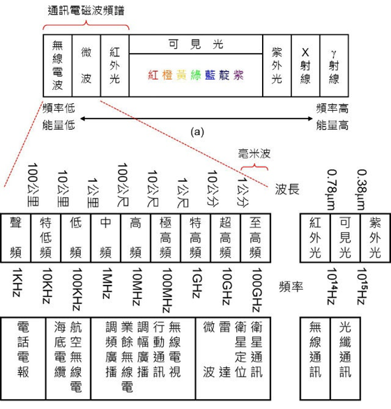
Fig. 312 shows the only electromagnetic wave range not yet developed for wireless communication is the tetrahertz region. As other lower frequency ranges were scrambled by 3G, 4G and 5G. Hence the future 6G generation will make use of the Tetrahertz band region with frequency in the order of T Hz.
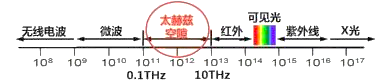
(Fig. 312) Range of electromagnetic wave
| Frequency / Hz | |||
| Name | Symbol | Generation | Magnitude |
| Cycle | Hz | — | — |
| Kilo | K Hz | 1G/2G | 1000 Hz /103Hz |
| Mega | M Hz | 3G | M Hz /1000KHz /106Hz |
| Giga | G Hz | 4G/5G | G Hz /1000MHz /109Hz |
| Tetra | T Hz | 6G | T Hz /1000GHz /1012Hz |
(Fig. 313) A frequency-based list of generations of wireless communication

(Fig. 314) A projected view of pre and post 5G time-sector
6G: IoE, Internet of Everything
As of today, 6G is still in the development stage (Fig. 314). According to assumption, data transmission quality of the future 6G network should reach a mobile download rate of 1 T Bps (8T bps) by 2021. Commercial roll out by 2030. The major application of 6G is not aimed at attaining extreme speed of “people to information”. In fact, using 0.01 second to download a 4G 4K movie by 6G smartphone as opposed to 1 second using a 5G smartphone seems to have no significant cost-effectiveness.
(Fig. 315) Some predicated 6G network service users
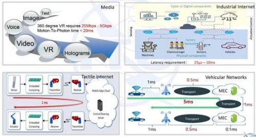
Limited by the 10 ms latency feature of the 4G technology, existing 4G technology is incapable of guaranteeing error-free applications of IoT, remote-control medical operation (internet of contact), driverless auto-driving (internet of vehicles), holographic media etc. If AI / big data combination fell short of the demand of interference-free and extra low latency, 5G driverless navigation would not be 100% safe. 6G technology can fulfill this blind spot.
Broadly speaking, 6G communication enables “people to everything” instantaneous interactions,
In April 2019 Finland Levi held the first international 6G wireless summit. Huawei, China Telecom, ZTE and Tsinghua experts proposed a very innovative and aggressive idea of planting numerous low altitude mini satellites as 6G base stations for global coverage. This is probably a feasible way of doing away with difficulty in building adequate territorial ground stations. Further investigations needed for actual global feasibility.
6G Innovative media:Remote 3D parallax holographic real time video wireless broadcast
(i) 2-dimensional and pseudo 3-dimensional viewing
We are accustomed to view a 3-dimensional object as a 2-dimensional image (Fig. 316). Especially when we view a TV program, we never ask ourself why actors all appear flat on the screen and not what they should actually looked like, unfolding depth, right or left 3D feature, in front of us.

(Fig. 316) A 3D street scene with depth becomes flat on a TV screen
In a real 3D world, when we look at a stationary solid object and move left, we will find the object seems to move to the right. Further movement to the left and we can see the right side of the object which we cannot see when it is in front of us. The converse is also true. This basic concept due to depth is called parallax (視差): “eyes to the left, object to the right and vice versa”. A 2-dimensional image of a 3-dimensional object lacks depth. A 3D object possesses parallax but not a 2D flat object or image. Reproducing depth of an object as a dimension of the image requires a completely different kind of technology.
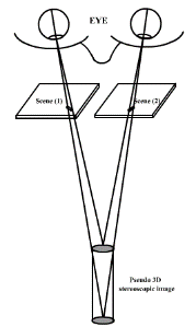
Although the concept of parallax is simple, until now, the technology needed to reproduce a 3D 360o colour image with parallax is still not available. In the past, people used the simple technique of “stereo-viewing” to obtain a pseudo 3-dimensional viewing (Fig. 318). This technique is called “stereoscopic imaging” which is totally different from “3-dimensional imaging”. The method is by eye-focusing, commonly called cross-eyed focusing (內斜視眼,鬥雞眼), of 2 images of the same object with the same size but with slightly different positions.
Project (13): Stereoscopic viewing
Materials: hand lens (x2), a stereoscopic picture as shown below.
 |  |
(Fig. 317) A picture for stereo-viewing
Procedure:
Print the above photo on a A4 size paper and view it with two hand lenses as shown in Fig. 319 or use a stereo-viewer as shown in Fig. 320. View with “cross-eye”.
 | 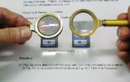 |
| (Fig. 319) A two hand-lens stereoviewer | |
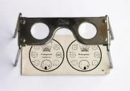 | |
| (Fig. 318) Pseudo 3D stereoscopic viewing | (Fig. 320) A commercial stereo-viewer |
View the video clip of Fig. 321. You should see pseudo 3D images by naked “cross-eyes”. Good luck!

(Fig. 321) A stereoscopic scenery video clip
Today, 3D movies used either red and blue light or polarized light to form images and we have to wear red/blue glasses or polarized glasses to view the movie. Computer -based Virtual Reality (VR) viewing with special eye mask can view 3D dynamic video clips and is becoming a prevailing hot leisure activity. All in all, these so-called 3D viewings are not truly 3-dimensional, as the important element of parallax is absent.
(ii) Holography (全息影像)
To reproduce images with parallax or depth need technologies other than light-sensitive technologies such as CMOS photo imaging. Technology for this purpose has not yet been fully developed. It appears Holographic imaging is the only future means of development. Digital optical fibre or wireless 3D parallax holographic image transmission requires zero latency and 6G technology nicely fulfill this important requirement.
Holography literally means the imaging of all information (Greek holo means whole) gathered from the object, namely (i) reflected wavelength (colour), (ii) reflected amplitude (contour, brightness) and (ii) phase difference due to various points on the surface of the object (unevenness of object). Ordinary photography records only information (i) and (ii), hence ordinary photos lack depth which is primarily caused by phase differences of reflected light from different positions of the object. All ordinary photos are 2-dimensional, flat and smooth with no parallax.
Luckily our magical eyes are able to detect all of information and we can see real objects as true 3D images with parallax. In addition, seeing with only one eye deters the extent of parallax and abates distance judgement. This may cause detrimental harm to drivers.
Reflected ray from different positions of a solid object inherited variations of wavelength, amplitude and phase differences. Phase difference or phase shift, of positions of object cannot be recorded simply by direct recording of the reflected ray. It has to undergo interference of two kinds of reflected rays (one is called the reference beam) from the same monochromatic light source, called a “coherent monochromatic light source”.
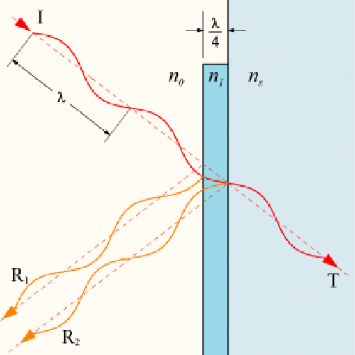
View internet information about applications of interferences of electromagnetic waves, especially the anti-reflective coating of eyeglasses and camera lenses (Fig. 322, 323, 324, 325) using odd multiples of quarter wavelength thickness of coating to induce destructive interference of reflected light.
(Fig. 322) Quarter-wave coating of camera lens to eliminate light reflected from the lens surface
 |  |  |
| (Fg 323) Eyeglasses with (right) and without anti-reflective coating | (Fg 324) Scene captured by camera without reflective coating | (Fg 325) Scene captured by camera with reflective coating |
Holography is a kind of imaging technology recording all embedded information of wavelength, amplitude, and phase shift of electromagnetic wave reflected (or refracted) from objects. A coherent monochromatic light source (usually a laser beam) is required for recording all of the three kinds of signals to form a hologram. When the hologram is irradiated with the same wavelength of laser beam, a true 3D real image (not virtual) with parallax will be formed (Fig. 326).
(Fig. 326) A video playback of holographic 360o real image
A traditional formation of holographic image is illustrated as follows (Fig. 327):
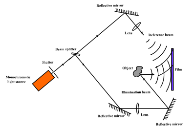
(Fig. 327) Hologram formation by splitted laser beams

(Fig. 328) A beam splitter generates reflected ray with phase shift of p
A coherent monochromatic light source, usually a laser beam, irradiates a one-way mirror (half-silvered mirror or beam splitter) and forms a reflected ray with a phase shift of p (reference beam) and a refracted ray having the same phase as the source (Fig. 328). The reflected ray, acting as the illumination ray, illuminates the object and bounces back to a special light-sensitive film, while the refracted ray is reflected by a second mirror and acts as the reference beam. It heads, simultanouely with the bounce-back illumination ray, towards the same sensor film.
The two rays form an interference pattern on the film which is called a “hologram”, recording all the e.m. wave information signals sent from the object. A hologram cannot be viewed by normal light, it has to be irradiated by a laser beam of the same wavelength as the coherent light source in order to reproduce a real 3D image with parallax (Fig. 329). If the reference beam and the reflected ray come from two different light sources, interference will not occur. Hence a coherent source is required.
Also, images formed by a plane mirror are virtual and erect, they cannot be formed on a screen and lack parallax. On the other hand, images formed by objects placed far away from a convergent lens can form on a screen. They are real and inverted and may or may not possess parallax. They are best viewed 25 cm away from the focus.
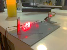 |
(Fig. 329) A hologram iRradiated by a laser beam forms real 3D image
Theoretically, a coherent red, green and blue laser beam can form a hologram that can reproduce a coloured, real 3D image with parallax of the object. Unfortunately, it is still not workable with present technology. However, using white light, i.e. ordinary light, to make white light holograms had been widely used in fabricating credit card security labels (the familiar flying eagle label, Fig. 330) or hologram stickers (Fig. 331).
Japan rolled out the first animated holographic video “Hatsune Miku” (初音) in 2008 (Fig 332). Still a lot fall short of real time actual singer holographic 3D image with parallax wireless broadcast reception. In 2017, Japan pioneered the media technology field in reproducing a 3D playback scenery of the past popular singer鄧麗君 (Fig. 333). It seemed to be a successful attempt of reproducing a past 3D video clip in space, but later revealed actually, by TBS, to be a new kind of MR (Mixed Reality) technique. In short, remote wireless holographic real time broadcast is a matter of our next generation.
 |  |
| (Fig. 330) Flying eagle security hologram label | (Fig. 331) Hologram sticker |
 | |
| (Fig. 334) A shot in a TV program showing a girl. If you want to see the girl’s right ear, you cannot see it even if you move your headto the left | (Fig. 335) The same frame using 6G holographic wireless broadcast, you can have a glimpse of the girl’s right ear if you move your head to the left. |
An imaginative 6G holographic 3D parallax TV screen show could be depicted as in Fig. 334 and 335. One has to move to-and-fro to appreciate the parallax nature of a stationary picture of a 6G holographic TV show.
(iii) Effect of a 3D “holographic” display in a 2D video – Directional pixel technology
As a holistic package of real time wireless data transmission of wave length, amplitude and phase difference of reflected e.m. wave is still not available at our present time of technology, people turned to new ways of doing away with the dimension of phase difference other than the traditional method of stereoviewing by wearing glasses.
The only requirement on the viewer’s part is not to wear any kind of glasses. As to the TV screening technology part, a developing technology called the “Directional pixel technology” was commercially pioneered in 2020 (www.realfiction.com/innovation).
A screenshot of a publicizing video clip enhancing the 3D feature of the “Directional pixel technology” display using a TV set (Fig. 336):
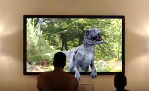
(Fig. 336) An ECHO 3D display shown on a TV set

(Fig. 337) An introduction to the ECHO 3D directional pixel technology
 |  |
(Fig. 338) Evenly illuminated conventional TV sereen is blanketly viewed | (Fig. 339) ECHO’s directional pixel projecton isselectively viewed |