Symbol: |
| or |
|

Unit of coding is ohm, Ω. Normal range of value of resistance is very wide, from less than 1Ω to 10 MΩ。
| Colour code | Number | No. of times factor |
| 黑(Black) | 0 | ×1 |
| 棕(Brown) | 1 | ×10 |
| 紅(Red) | 2 | ×100 |
| 橙(Orange) | 3 | ×1000 |
| 黃(Yellow) | 4 | ×10000 |
| 綠(Green) | 5 | ×100000 |
| 藍(Blue) | 6 | ×1000000 |
| 紫(Violet) | 7 | ×10000000 |
| 灰(Gray) | 8 | ×100000000 |
| 白(White) | 9 | ×1000000000 |
Colour code | Accuracy |
金(Gold) | ± 5 % |
銀(Silver) | ± 10 % |
透明(None) | ± 20 % |
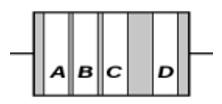
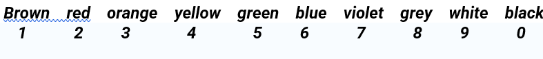
Colour A represents the 1st digit.
Colour B represents the 2nd digit.
Colour C represents the number of times factor. Brown means 10 times, red means times 100 times, orange means 1000 times etc.
Colour D, if exist, represents percentage accuracy. In the absence of this colour, the resistor is assumed to have an accuracy of ±20%。
Example: A resistor with a colour coding in series like this: yellow, violet, red, gold
First colour represents 4, second colour represents 7, third colour means 102 (or 100 times), the fourth colour means it has an accuracy of ±5%.
Hence the resistor has a value of 4,700 Ω and with an accuracy of ±5%. The range of value of resistance lies between 4,465 Ω and 4,935 Ω.
(Need to remember by heart the colour coding in an ascending manner. This helps us to obtain a value of resistance just by looking at it)
Project (2) Testing colour coded resistors
Materials: DMM, various carbon resistors.
Resistor | Value by inspection / Ω | Wattage/Ω | Accuracy | Value by meter/ Ω |
1 | ||||
2 | ||||
3 |
Various form of fixed resistors:
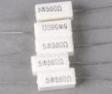
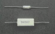
Type | Carbon film resistor | Metal film resistor | Wire wound resistor | Cement resistor |
Diagram |
(Beige brown based) |
(Blue based) |
|
|
Range of value | A few Ω to 10 MΩ | A few Ω to 10 MΩ | 1Ω to 500 KΩ | 1Ω to 100 KΩ |
Range of wattage | 1/8W to 1W | 1/8W to 1W | 1/2 W to 10 W | 1W to 20W |
Accuracy | Mostly 5% | All 1% or even less | About 5% | About 10% |


![]()
![]()


 |
 |
 |
|
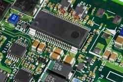
(Fig. 115) SMT (motherboard of computer) |
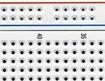
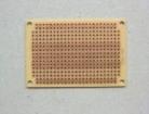
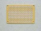
(Fig. 116) Universal thro-hole cicuit board (front/back view) |
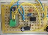
(Fig. 117) Components soldered onto a circuit board. |
Work of completing the circuit based on soldering components should be started after careful considerations of suitable locations and points of junction. This needs some experience, do not think the first attempt could be perfect. General practice uses either (i) Thro-hole printed circuit board or (ii) Thro-hole universal circuit board.
(i) Thro-hole printed circuit board (PCB)
The method is used for mass production of circuit boards.
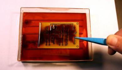
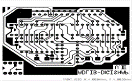
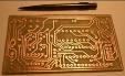
For, say 10 or more pieces of board, the traditional method of printing the circuit on a copper plate backed by an insulating bakelite or fiber board, is normally used. The circuit is either screen printed (hence its name) or by using a symbol stencil transfer coupled with black oil-based sign pen to fine tone the detail conduction connections (Fig. 118). The unwanted copper (unmasked part) will be dissolved by using iron (III) chloride (redox displacement reaction, Fig. 119). Holes at suitable positions will be drilled to accommodate components and connecting wires (Fig. 120). Finally, components are inserted into appropreiate positions and solder is applied at the holes to complete the job. Unfortunately, chemicals and tools for this old method become less available for the hobbyists. Instead, commercial kits are more available e.g. a frequency counter kit with PCB and various components (Fig. 121)
 |
 |
 |
 |
| (Fig. 118) Circuit printed on a copper plate backed with bakelite or fiber board. The masked part is prevented from corrosion. | (Fig.119) Strong iron (III) chloride solution is used to dissolve the exposed copper part by displacement reaction: Cu + 2Fe3+ → Cu2+ + 2Fe 2+ | (Fig.120) A finished PCB |
(Fig. 121) A commercial DIY frequency counter kit with PCB and various components. |
Recent method employs photo-sensitive negative film. (Fig.122, 123), often used industrially. Photo-sensitive copper plate is another alternative. Nowadays a convenient way called (Press-n-peel) film method (Fig. 124) is getting popular. Need to order from the internet, details from web search.
 |
 |
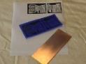  |
| (Fig. 122) Negative film | (Fig. 123) Finished PCB | (Fig. 124) “Press-n-peel” technique |
The above methods, in fact, had been in use for more than 10 years. Nowadays, computer assisted techniques were employed in most sectors of industry, PCB making is no exception. Coupled with software and a computerized engraver, a handy and sophisticated engraved PCB, with no corrosion medium, can be made with a piece of copper clad (Fig. 125, 126, 127).
 |
 |
 |
| (Fig. 125) Computer assisted design | (Fig. 126) Circuit engraving |
(Fig. 127) Finished engraved copper clad |
View the following video clip for details:
Computer assisted PCB making
If only a few pieces of circuit boards are required, it is not necessary to go through tedious procedures as mentioned by the above methods. Rather, a more convenient way is to use a universal tho-hole multi-purpose circuit board to tackle the job, introduced as follows:
(ii) Thro-hole multi-purpose circuit board
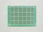
This method is mostly adopted if a few circuit boards are required. Universal thro-hole circuit board (Fig. 128) is available from most electronic component shops, there is no need to homemade it. The back-side of the board is covered with copper linings with holes. Basically, it can accommodate all kinds of electronic components. Positions to insert them on the front-side requires a bit of critical thinking gathered from field experience. This takes time, no short cut.
 |
 |
 |
| (Fig.128) Universal thro-hole circuit board | ||
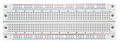
Project (4) (i) Testing mounting methods of various electronic components on a breadboard. (ii) Mount and solder an 8 pin DIP IC socket on a universal thro-hole circuit board follow by inserting a LM 358 Op Amp IC Materials: DMM, breadboard, 8 pin DIP IC socket, LM 358,soldering iron and other accessories
e. Light Emitting Diode, (LED)
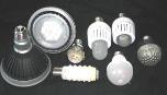
Technology of high wattage rating (> 1W)LED experienced very fast development over the past decade, especially those aiming at economic and bright illuminating appliances substituting the incandescent or fluorescent lamp lightings (Fig. 126). LED lamps are readily available in the market. The luminous intensity of a 7W LED lamp is equivalent to a 60W incandescent lamp.
Similary, small wattage ratings 3 mm and 5 mm LEDs (Fig. 128) had dominated the electronic component market for many years. Advantages of these LEDs include: (i) low activating voltage (< 3V) and low current consumption (5 mA), (ii) long life time, (iii) small size, (iv) super-bright LED using the same current consumption is readily available nowadays. Disadvantages include (i) needs DC voltage, (ii) fragile fusible/breaking voltage compared with incandescent counterparts which are more tolerating.
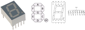
Small wattage rating LEDs almost replace traditional panel neon (Fig. 129) or incandescent lamps (Fig. 127). Another type of popular LED is the 7 segment LED arranged to form a tilted Chinese letter (日) for dispaying numerical value and alphabets. They are classified as common cathode or common anode types (Fig. 130).
 |
 |
 |
 |
 |
| (Fig. 126) | (Fig. 127) | (Fig. 128) | (Fig. 129) | (Fig. 130) 7 segment LED |

 |
 |
| (Fig. 131) A Dip micro-toggle switch | |
| Micro-switch (1) stands for ON and (0) stands for OFF | 7 segment LED display | ||||||
| a | b | c | d | e | f | g | |
| 1 | 1 | 1 | 1 | 1 | 1 | 0 | 0 |
| 0 | 1 | 1 | 0 | 0 | 0 | 0 | 1 |
| 1 | 1 | 0 | 1 | 1 | 0 | 1 | 2 |
| 1 | 1 | 1 | 1 | 0 | 0 | 1 | 3 |
| 0 | 1 | 1 | 0 | 0 | 1 | 1 | 4 |
| 1 | 0 | 1 | 1 | 0 | 1 | 1 | 5 |
| 0 | 0 | 1 | 1 | 1 | 1 | 1 | 6 |
| 1 | 1 | 1 | 0 | 0 | 0 | 0 | 7 |
| 1 | 1 | 1 | 1 | 1 | 1 | 1 | 8 |
| 1 | 1 | 1 | 0 | 0 | 1 | 1 | 9 |
(Fig. 132) 7 segment pin connections and corresponding display of numbers
f. Integrated Circuit, IC, chip
Devlopmental path of Integrated Circuits
An introduction to Integrated Circuits
Integrated Circuit, IC, is a kind of complicated micro-electronic device, using special technology to embed required semiconductors, resistors capacitors, inductors and wiring for a circuit on a small medium substrate and finish with a special package.
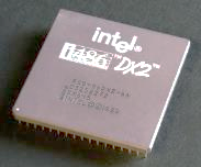 | 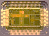 |
| (Fig. 133) CPU of a computer is a sophisticated IC | (Fig. 134) inner structure of a CPU |
Advantages of IC
Features of IC include: extra small and light, only a few leads, long lifetime, highly stable and reliable. Using silicon as the main ingredient is a very cost-effective way for mass production, resulting in extremely low cost and helps to promote consumers’ quest for amateurish as well as professional electronic design innovations. Employing ICs for circuit design upgrades transistor density hundred or thousand times. Countless applications of IC were found in mobile phones, TV sets, computers (Fig. 133, 134) etc.
Classifications of IC
(i) According to structure and function:
Analogue IC is also call Linear IC or Operational Amplifier (Linear, Op Amp). Usage of these kind of IC is to generate, amplify and process all kinds of analogue signals, amplitude of which varies with time. Sound signals from semiconductor radios and video signals from magnetic hysteresis playbacks were vivid examples of the past decades. In short, for amplification function, input signals and output signals bear simple mathematical proportionality, hence the name Linear.
Digital IC accepts, generates and process only digital signals which can be in the form of propagating (0 1) square waves or discretely scattered (0 1) binary bits. Countless application examples are found in smartphones, digital cameras, computer CPU, digital TV sets etc. Electronic logic gates are used in the IC chips to process digital sound and video signals. Importance of digital IC exceeds that of Op-Amp IC and dominates the current IC chip market.
(ii) According to fabrication technology:
Fabrication of IC is classified according to massive embedment of semiconductors (Transistor IC) or having the full circuit constructed on a single piece of silicon or other semiconductor, then enclosed in a package with connecting leads (Monolithic IC). Thick or thin Monolithic ICs are available for different purposes.
(iii) According to integrated density:
SSIC (Small Scale Integrated Circuits)
MSIC (Medium Scale Integrated Circuits)
LSIC (Large Scale Integrated Circuits) etc
(iv) According to types of conducting gates:
Conducting gate of IC is classified into two types (i) Dual-gate IC or (ii) single-gate IC, they all process digital signals. Fabrication of dual-gate IC is complicated, dissipation of power is high, examples are TTL, LSTTL, STTL etc. On the contrary, fabrication of single-gate is simpler, dissipation of power is low, suitable for LSIC mass production. Examples single-gate are CMOS, NMOS, PMOS etc.
Applications of IC
Military grade ICs have stringent specifications to meet large range of temperature variation and reliable resistance to noise interference. Next best graders are those for industrial and consumer usage. They are widely used in computer manufacture, communication facilities, smartphones, TV sets, cameras, audio appliances etc. They get into our daily life utilities in every opening, monopolizing the main application field.
Packaging of mainstream IC
(i) DIP (dual in-line package).
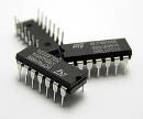 | 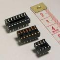 |  |
| (Fig. 135) 14 pin DIP IC | (Fig. 136) 16,14 and 8 pin IC socket | (Fig. 137) LM 358 pin assignment |
IC leads protrude from both sides of the package as pins. Packaging materials include plastics and ceramic, i.e. PDIP and CerDIP. Dual array direct insert IC either inserts into a socket or soldered onto a circuit board. DIP insert type packaging is the most popular consumer item, well received by amateur electronic hobbyists. Most Op-Amp ICs are of the DIP type, e.g. LM 358 or mA 741 etc.
(ii) TO – 220 packaging
“TO” stands for “(Transistor Outline)”
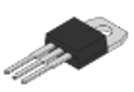 | 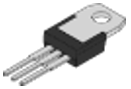 | 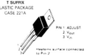 |
| (Fig. 138) Front view of a TO-220 package | (Fig. 139) back view of a TO-220 package | (Fig. 140) Motorola LM 317 |
TO – 220 package IC has 3 pin leads: 1, 2 and 3 (Fig. 138, 139 and 140). TO – 220 pagkage has one feature: there is a thick backing metal plate with one hole, for mounting convenience and heat dissipation. Most medium power voltage regulators are packed with TO – 220 type. Examples are LM 317, 7805 7905 etc.
Common IC symbols
| Name | Symbol |
| Op-Amp | 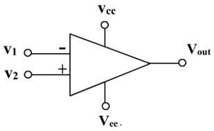 |
| Regulator | |
| CMOS | 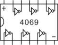 |
| TTL | 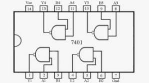 |
| Same symbols are used for CMOS and TTL, differentiated by labelling. CMOS uses 4XXX 4-digit label, TTL uses 74XX | |
Popular IC used in instrumental design
Nowadays, discrete transisitors are seldomly used for design of electronic circuitry, instead, ICs are commonly employed mainly because a single IC suits a lot of applications while the function of a discrete transistor is limited by its inherent inadequacies.
Advantages in using IC for circuit design:
* High input resistance, low noise level, low power dissipation, inexpensive.
* A single IC can embed tenths or hundredths of various types of semiconductors.
* “Black-box operation” is a major advantage of IC. Circuit designers need to know only the nature of input signals and the output demands, principle of coupling between individual parts of the IC circuitry can be ignored.
* Normally, all ICs have built-in protective circuits.
* Unlike transistors, all ICs have designated functions.
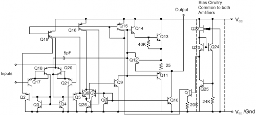
Internal structure of Dual Op-Amp LM 358 (each chip has two identitical units):
(Fig.141) Structure of one unit of LM 358 |
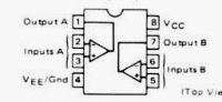
(Fig. 142) Dual Op Amp LM 358 pin assignment |
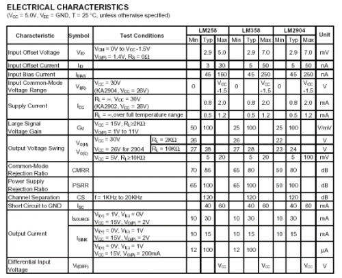 (Fig. 143) LM 358 electrical characteristics
Military grade: LM 158 (-55oC to +125oC)
Industrial grade: LM 258 (-25oC to +85oC)
Consumer grade: LM 358 (0oC to + 70oC)
Professional circuit design needs reference to parameters of electrical characteristics as outlined in Fig. 143. Input/output conditions have to be carefully considered in every part of the circuit. However, amateur hobbyists usually do not follow rigorously as such and use point to point AVO (ampere, voltage and ohm) testing, or more precisely using an oscilloscope to obtain basic AVO parameters followed by the “trial-and-error” first principle method to complete the design. Commonly used ICs for circuit designs are: LM317 for voltage regulators, 555 for timer, LM 358, LM 741 for Op-Amps. CMOS 4049 for oscillators, LM 3914 for bar/dot display, TTL 7448 or CMOS CD 4511 for 7 segment LED drivers.
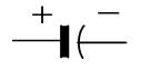
g. Capacitor, condenser
As its name implies, capacitor is used to store electrical charges.
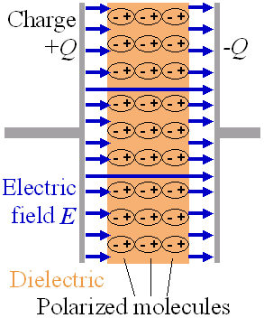
A simple capacitor can be constructed by using two separated metal plates (conductors), between which is placed an insulating polarizable dielectric. Unit of capacitance is “Faraday” symbol F. Electrical energy is stored between two conductors with the help of electric field. Electrical charges on the two conductors are equal but with different polarity, i.e. one is positive (+) and the other is negative (-).
Direct current (DC) cannot pass through capacitors, but alternate current (AC) is possible.
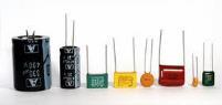
(Fig. 144) A variety of capacitors used in electronic technology

![]()
Working principle and capacitance of a capacitor
Capacitance (C) of a capacitor refers to the quanity of electrical charge (Q) stored when the voltage or potential across the two plates is unity, i.e V = 1.
According to international SI unit, if a potential difference of 1 V is applied to the two plates of a capacitor, the quantity of stored eletrical charge is said to be 1 coulomb and the capacitance of this capacitor is said to have 1 Faraday, 1F. In practice, a Faraday is a pretty large unit. Normally, capacitance of a capacitor is expressed in number of milli-Faraday, mF, (1 mF = 10-3 F), micro-Faraday, µF, (1µF = 10-6 F), nano-Faraday, nF, (1nF = 10-9 F) or pico-Faraday. pF, (1pF = 10-12 F). |
|
Identification of capacitor
Colour coding is not adopted, capacitance values are printed on the capacitor.
| Classification | Photo | Common value / label | Polarity/ feature/ breakdown voltage | Usage/ remark |
| Electrolytic capacitor |  | 1–5000 µF | With (+) and (-) terminals / 6 – 400 V DC | * filtering dc output after rectification * charge storage * reasonable price |
| Ceramic capacitor |  | 1 pF – 1µF 104 means a value of 10×104 pF =100,000 pF = 100 nF = 0.1 µF | Non polar / high voltage breakdown (~1000 V DC) | * for coupling * for oscillators * inexpensive |
| Plastic film capacitor |  | 1 pF – µF | Non polar, high insulation resistance, excellent frequency characteristics (wide range of frequency response) Classified according to types of plastic material used as (mylar film), (polystyrene film), (polypropylene film) and (polycarbonate film) | * for precision analogue circuits * a bit expensive |
| Tantalum electrolytic capacitor |  | 1 pF – 1µF | Non polar, high voltage breakdown Characteristics similar to ceramic capacitors, for energy storage, uses rare metal tantalum, high quality capacitance, suitable for micro-scale design | *for smart- phones, USB. *for efficient data transfer |
Project (5) Testing a variety of capacitors
Material: Needle-type multimeter, a variety of 1 – 2000 µF electrolytic capacitors
A quick test for electrolytic capacitors
DC current cannot pass through capacitors. If a capacitor allows DC current to pass through, it is said to be brokendown. Electrolytic capacitors are easier to test for their non-conducting conditions than other capacitors. Method usually employed is as follows:
Select a needle AVO multimeter. Set to measure the resistance option and fix the measuring range at (x100). Touch the (+) and (-) terminals of the capacitor (>10mF) at the same time by the meter’s testing probes. Reverse the testing situation repeatedly. If one observes the needle rises and then falls rapidly, the testing capacitor is functioning normally. On the contrary, if the needle fais to fall, the capacitors are said to be damaged.
Application of capacitors in circuit design
Capacitor can screen DC current. When it is connected to a battery, the two terminals pick up charges quickly. Upon fully charged, there will be no current flow. However, capacitors allow AC current to pass through. This is because applying AC current to a capacitor results in an alternating continuous charge/discharge pattern which functions like a pulsing agent for flowing.
(i) Filter capacitor: If a DC current has pulse or peaks, they could be smoothed by large capacitance capacitors. Electrolytic capacitors are very suitable for the job. Capacitors as such are called filter capacitors. They are widely employed in after AC rectification treatment for DC voltage output. The example of half-wave rectification followed by filter capacitor to obtain near DC (still have ripple voltage) voltage is very typical:
| AC current converted to DC current (half-wave rectification) | 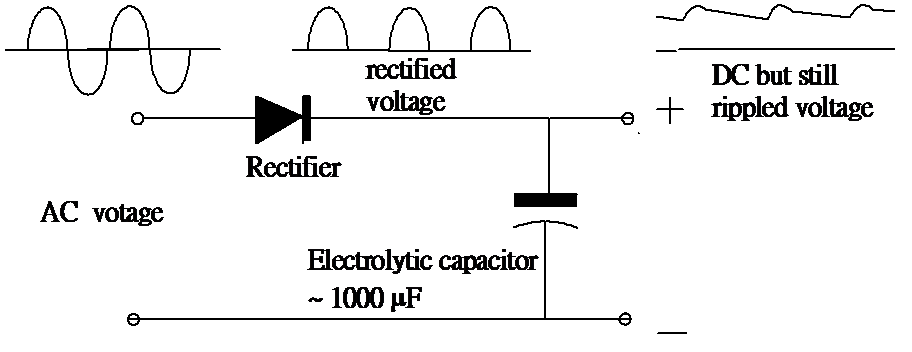 |
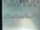 | 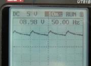 |
| (Fig. 145) Wave form after half-wave rectification | (Fig. 146) Filtered wave form |
(ii) Oscillator capacitor:
Apart from acting as a rectification filter, an even more important application of capacitor is to form an important component of oscillating circuit to generate functional wave form signals. The very basic principle of computer, no matter how complicate it may be, can be broken down into an electronic ON/OFF device coupled with a precise square wave propagating signal to trigger all kinds of operations. The following diagram shows a popular Op-Amp oscillator, called relaxation oscillator, generating a propagating signal of square waves. Besides providing signal amplitude, more importantly it functions as a time base, commonly called as a clock.
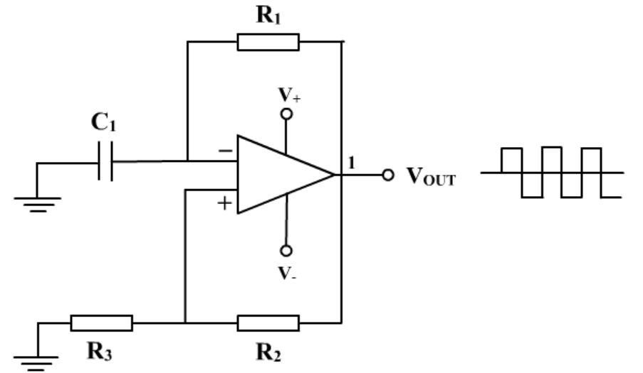
(Fig. 147) Relaxation square wave oscillator
Assuming the above oscillating circuit, let R = 1.5 KW,C = 0.1 mF,the frequency, f, of the square wave signal generated is expressed as :
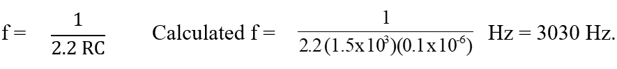
The time base generated can also be expressed as 3030-1 or 3.3 x 10⁻⁴ sec per cycle. Time base expressed as frequency (Hz, cycles per sec) is commonly adopted as opposed to sec per cycle.
Refer to Topic 8.3 (Practical analogue circuits) for more detailed introduction to the principle and application of relaxation oscillator.
h.Inductor
Inductor is also called coil. Inductor is classified as (i) air core and (ii) iron/ferrite core.
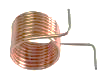 |  |  |
| (Fig. 148) air core coil | (Fig. 149) Ferrite core coil | (Fig. 150) iron core coil, commonly known as transformer |


When electric current passes through coils of metal wire, apart from acting as a resistor, it also generates magnetic field. This electromagnetic phenomenon is particularly important when AC current is used.
DC current and inductor
When the author was still a primary school boy, he often performed this simple scientific experiment for fun: wrap an iron nail with coils of electrical wire and connect the two terminals of the wire to a battery. Place the setup near another iron nail. What would you observe?
 |  |  | |
 | |||
(Fig. 151) Electromagnetic effect | (Fig. 152) Electromagnetic flux and magnetic poles | ||
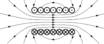
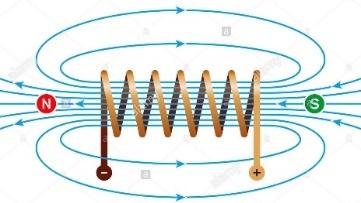
DC current establishes magnetic lines when passing through a metal wire. This phenomenon is called “electromagnetic effect”. The magnetic flux (quantity and strength of magnetic lines) obeys the “right hand screw rule” (Fig. 151). If the wire is made into a number of turns, i.e. to form a coil, the magnetic lines will superimpose and generates a magnetic field, possessing a magnetic North and a magnetic South pole. A coil as such is called an Inductor, and the coil behaves like a normal magnet (Fig. 152). Note that the labeling of magnetic line’s pointing direction is important because it concerns with electromagnetic formulae calculations. The conventionally adopted way is an arrow through the medium pointing from the North pole to the South pole (Fig. 152). Similarly, electric field’s pointing direction is from the (+) to the (-) pole.
Electromagnetic flux takes time to rise from zero. When it starts to rise (or change), the coil itself will induce an e.m.f. (Faraday’s law) which is called “self-induction”. This new e.m.f. degenerates the applied voltage and lowers the voltage across the terminals of the coil. Hence this e.m.f. is called “back e.m.f.”. This is unavoidable. Development as such repeats until a steady state is reached. At such point the current and the established magnetic field becomes steady. When a coil is acting as an inductor, itself is short-circuited. Like a resistor, situation like this generates heat. Thus, induction is a kind of double-edged sword, it creates magnetic field but at the same time also generates unwanted heat which needs to be dissipated.
Induction finds an important usage in medical instrumental design. The well received MRI (Nuclear Magnetic Resonance Imaging, 磁力共振成像) provides very high definition of human internal organ structure sliced image which is a very helpful tool for diagnosis. MRI instrument needs extremely low temperature (liquid helium) so that superconductivity (zero resistance) can take place. If resistance occurs, the huge amount of current required for the operation of the instrument will result in large amount of heat making temperature lowering impossible (Fig. 153, 154).
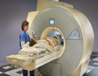 |  | |
| (Fig. 153) MRI instrument | (Fig. 154) MRI image of the head | |
Inductors in electronic circuit design do not use DC current. Very weak AC current, e.g. radio frequency from antenna was used in air core coils for frequency selection, through resonance coupling, in the era of radio broadcasting. Nowadays, AC current is used in transformer for stepping up or lowering down power supply voltage. Transformer used consists of two iron core coils, one is called primary coil and the other secondary coil.
Nature of the resistance of an inductor is different from that of a resistor, because of the involvement of back e.m.f, Hence, it has a special name: impedance, Z. Unlike W, Z is a complex number. School level science syllabuses do not include the study of impedance. For most situations in the absence of coil and capacitors, resistance is generally used. Some would use impedance for the sake of accuracy, but does not mean resistors impart impedance. The two terms carry the same meaning for a resistor.
Superconductivity and MRI equipment
Currently, most MRI machines use low temperature superconductors (employing liquid helium) for adequate electromagnetic flux generation. As using the same technology for making room temperature superconductors is unrealistic for the coming future, people turned to the re-discovered monolayer of graphite, or called as graphene. The two researchers who succeeded in the separation of graphite layers won the 2010 Nobel Prize in Physics. It is hoped that the exceptional electrical conductivity feature of graphene and its derived products can one day be developed into a prototype of room temperature near-superconductor, suitable for fabricating MRI equipment.
AC current and inductor
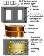
AC current and DC current have completely different results when passing through a coil of copper wire. AC current when passing through an insulated (enamel coated) copper coil wrapped round an iron core quickly establishes a steady fluctuating magnetic field. The magnetic flux is expected to totally pass through the iron core. The iron core is actually made by stacking sheets of silicon steel in the shape of 口or letter E turned 90o (Fig. 155) and not a single solid steel core. This avoids eddy current and hysteresis build up. Another coil of enamel wire wrapped at the other end will pickup an induced secondary voltage. The first coil is called the primary coil while the second one is called the secondary coil (Fig. 156). A setup feeding the primary coil to a power supply of AC 50 Hz is called a transformer (Fig. 157).
 |  | |
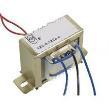
| (Fig. 155) Structural diagram of a transformer | (Fig. 156) Symbol of a transformer | (Fig. 157) A commercial transformer |
AC current passing through the primary coil generates fluctuating magnetic fux (50Hz for most city power supply). The flux transmits in a “loop-the-loop” style within the closed iron core, converting the supply AC power to fluctuating magnetic fux without short-circuiting the setup. The magnetic flux will induce a secondary AC voltage which can be higher or lower than the power supply voltage (220 V in H.K.), depending on the number of turns of the secondary coil.
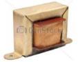
An inductor without a secondary coil is called a choke (Fig. 158). A choke is used to limit high frequency current and make way for the low frequency current or DC current. It is employed in precise filtering of rectified AC current to remove unwanted ripple interference for a clean DC current output (Fig. 159), compare with filtering of a half-wave rectified voltage by a single capacitor on page 50.
 |  |
| (Fig. 158) A filter choke. Primary coil only | (Fig. 159) Twin capacitor/choke combination for better filtering |
i. Transformer
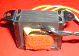
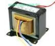
Transformer can be classified as (i) electronic transformer (for lighting, Fig. 160) and (ii) iron core transformer (for power supply and electronic circuits, Fig. 161).
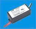 |  |
| (Fig. 160) Electronic transformer | (Fig. 161) Iron core transformer |
Only AC current is allowed for transformers.
Iron core transformers used in electronic circuit designs fall into two types:
(i) Step-down transformer
| Symbol: | |
This kind of transformer is mainly used for converting city power voltage supply, e.g. 220V AC to a low AC voltage supply for electronic appliances, usually coupled with rectification components to obtain low voltage DC supply for the designed circuit. Input coils are called primary coils and the output coils secondary coils.
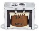
Unlike diagram of Fig. 155 showing a model for teaching purpose, Primary coils and secondary coils of commercial transformers are wound on the same hollow pillar-type core. The completed core is inserted into a pile of 90o-rotated E shape silicon steel sheets (Fig. 162). Input terminals are to be connected to the primary coil and the secondary coil outputs the required AC low voltage. Commonly available types of these transfomers are 6V, 12V, 24V etc. They are usually provided with a 3-pin output terminal, the middle one is supposed to be connected to ground and the other two terminals provide output voltages. For example, a 12V transformer can tap off two groups of 0V / 12V or a single 0V / 24V outputs (Fig. 163).
Lots of electrical appliances can be plugged directly into AC power supply for operation, it seems the whole instrument accepts 220V AC input. In fact, many are not, like battery chargers, TV sets etc, they all have built-in transformers to step-down the power supply voltage. It is because circuits of these appliances are designed not for high DC voltages, operating DC voltages are usually less than 50V.
A single-coil voltage supply transformer is called a “variac”. It can lower or slightly raised the power supply voltage (Fig. 164).
 |  |  |
| (Fig. 162) Structure of a commercial transformer | (Fig. 163) A 12V x 2 step-down transformer | (Fig. 164) A variac. Can lower or slightly raise the power supply voltage. Primary coil only. |
Today, quite a number of amateur hobbyists are nostalgic over the days of vacuum tube (electronic tube) era and found that these old electronic devices coupled with digital technique can delivery excellent audio effect, hence once popular vacuum tubes like EL34 (6L6), EL84 (6BQ5) etc became available again. This kind of power amplifiers (Fig. 166) employ vacuum tubes that need output transformer (Fig. 165) to drive the loudspeaker. Output transformer is a kind of step-down transformer, its function is to convert high voltage, high impedance output from the power electronic tubes to a low voltage, low impedance output which can match the impedance of the voice coil of a loudspeaker.
 | 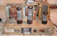 |
| (Fig. 165) An output transformer | (Fig. 166) Output transformer and vacuum tube electronic project |
(ii) Step-up transformer
| Symbol: | |
For a step-up transformer, number of coils of the secondary is more than that of the primary, resulting in an increase in output AC voltage. In the 50-70s of the last century, building a vacuum tube Hi-Fi amplifier was most amateur’s icon hobby and step-up transformer became a must for vacuum tube projects. This is because high DC voltage (~ 250V DC) has to be applied to the plate grid of a vacuum tube in order for it to function properly. Power source of electronic appliances nowadays use either battery or low DC voltage, usually not more than 50V DC. Hence step-down and not step-up transformers are used.
Project (3): Use a transformer to convert 220 V AC power supply to 12 V AC
Iron core of a transformer is built by stacking individual thin pieces of high-quality silicon steel sheets together. Pieces are insulated from one another. This way prevents building up of “eddy current” which generates unwanted radiation of heat energy. Today, transformers are purchased rather than self-made. They are not only inexpensive but are also of very good quality.
j. Rectifier
Rectification needs diode. A diode not only converts AC current to DC current, it is also used as a radio detector, converting amplitude modulated (AM) or frequency modulated (FM) radio waves to audio waves. The working principle of a diode is to allow only one direction of electron flow (forward bias), the other direction (reverse bias) is not allowed. If the anode of a diode is connected to the positive pole of a battery and the cathode to the negative pole, electric current flows. Current will not flow if the connection is reversed. Detector of a radio allows the positive cycles of radio waves to pass but not the negative cycles. The resulting wave form is then changed to audio waves for hearing.
The major field of applications of diode is rectification which turns AC current to DC current. Diode rectification circuits employ either (i) half-wave single diode or (ii) full-wave bridge diode (Fig. 167).
Single diode (half-wave rectifier) | Bridge rectifying diode (full-wave rectifier) | |
Photo |
1N34 diode |  |
| Symbol | 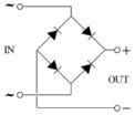 |
(Fig. 167) Half-wave and full-wave rectifier
Half-wave single diode rectification
During half-wave rectification, either the positive cycles or the negative cycles of the AC wave form will be cut off, only half of the wave form remains and the average output voltage is reduced by half. Conversion efficiency is low (Fig. 168).
 |  | 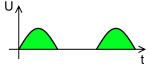 |
(Fig. 168) Half-wave rectification
Full-wave bridge rectification
Four diodes are needed for a full-wave bridge rectification (Fig. 169). All the wave forms of the positive cycle are retained and the conversion efficiency is some what improved.
|  | 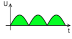 |
(Fig. 169) Full-wave rectification
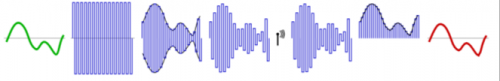
Project (4): Use an oscilloscope to display wave forms of (i) city power supply sine wave 220 V AC 50 Hz (Fig. 170), (ii) Half-wave rectification 4.5 V AC 50 Hz (Fig. 171) and (iii) Full-wave rectification 7.5V AC 100 Hz (Fig. 172).
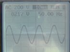 | |  |
| (Fig. 170) Power supply 220V AC sine wave | (Fig. 171) Half-wave rectification wave form | (Fig. 172) Fullf-wave rectification wave form |
Diode detector
During the period of 20-70s of last century, radio broadcast was done by analogue amplitude modulation (AM) wireless transmission. Operation of a radio at that time was first to receive radio signal from an antenna, then select the channel by an inductance/capacitance resonance circuit followed by detection by a solid-state diode or a vacuum tube diode and finally amplify the audio wave to drive a loudspeaker for hearing.
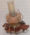
The most fundamental type of radio for a hobby starter is a crystal radio (Fig. 173):
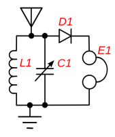
(Fig. 173) Circuit for a crystal radio
Coil (L1) and varable capacitor (C1) form a resonance circuit. Channel selection is done by adjusting C1, receiving a number of broadcast stations from the antenna.
Crystal radio
Selected frequency channel (f) is a resonate function of inductance (L) and capacitance (C), given by a formula of:
This frequency is technically called the resonance frequency of the parallel circuit of L1 and C1. It can be calculated by substituting values of L and C and is called as the frequency of a particular radio channel. For example, radio one of Radio Hong Kong has a broadcasting frequency of AM 640 KHz (Kilo-Hertz).
AM broadcasting (AM: amplitude modulation) and diode detection
 |
(i) Microphone turns sound waves to electrical audio signals.
(ii) Carrier wave of fixed frequency is generated, e.g. 640 KHz of Radio One, RTHK
(iii) Carrier wave and audio signals combined to form symmetric amplitude modulated (AM) radio wave.
(iv) Transmission tower radiates AM 640 KHz radio wave to a significant distance.
(v) Radio set picks up radio wave through an antenna and selects the channel using L/C resonance circuit.
(vi) Diode detector (D) cancels the negative wave form of the radio wave. IN34 is a popular diode of such kind.
(vii) Audio signal is reproduced and heard by using an earphone (E).
Homemade radio
FM broadcasting (FM: Frequency Modulation)
AM broadcasting, except for some special reasons, is substituted by FM broadcasting. As its abbreviation implies, FM is frequency modulation of audio signal and carrier radio wave. It enjoys the advantage of much improved sound quality, but also has a drawback of shorter transmission range. AM or FM transmission is gradually replaced by digital transmission with entirely different principle of transmission and reception.
Antique radio components
 |  |  |
| (Fig. 174) Honey-comb air coil for receiving radio signals | (Fig. 175) variable condenser for channel selection | (Fig. 176) single valve regenerative radio |
k. Zener diode
 | Symbol: |
If the reverse bias of a diode is too great, avalanche breakdown occurs and the diode may be permanently damaged by overheating. However, it was found that, as shown in Fig. 177, during the breakdown, the voltage across the diode varies little. This special property was made use of to fabricate a new type of diode that operates only on the steady reverse bias voltage range. This special diode was named after the inventor Clarence Melvin Zener in 1934, as Zener diode. In short, a Zener diode can clamp and stabilize a desired DC voltage within a short range with high accuracy. It is called as a voltage reference or a voltage regulator.
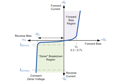
(Fig. 177) Breakdown region of a diode
Zener diodes work with a big voltage range from 2.4V to 200V. Commercially, a wide range of selection of Zener diodes with small voltage output differences, e.g. 3.3V, 3.6V, 3.9V, 4.3V, 4.7V etc (Fig. 178) are available. Typical power dissipation is 100 mW. Reverse current, in fact the conventional positive pole to negative pole electric current, is usually limited by a series resistor RS (Fig. 179). The fact that IS = IZ + IL implies current available for the load is shared by the Zener diode. As such, Zener diode is not a good choice as a power supply voltage regulator. Instead, it is often used in parts of a circuit in which p.d. has to be fixed at a certain precise level.
 | 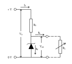 |
| (Fig. 178) Electrical characteristics of Zener diodes | (Fig. 179) A Zener diode voltage regulation circuit |
Voltage regulation is a very important concept in circuit design (Topic 8.3). Available voltage regulation electronic component includes Zener diodes and IC voltage regulators. Unlike Zener diodes, IC voltage regulators provides both positive and negative voltage regulations. Their available models not only provide a range of selection of current outputs (100 mA, 1 A and 1.5 A) but some also provide adjustable regulated voltage outputs. They have excellent electrical performances. Accreditation goes to the built-in short citcuit protection design. Internal structures of voltage regulator ICs are complicated and normally include a number of Zener diodes. However, they are not much more expensive than Zener diodes. Hence voltage regulator ICs are more suitable for power supply voltage regulation than Zener diodes.
l. Switch
Switches used in electronic projects include the following three types:
(1) Toggle switch
| Symbol: | This type of switch is also called SPST toggle switch (single-pole single-throw toggle switch) | |||
 | 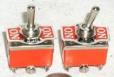 |
| (Fig. 180) SPST toggle switch | (Fig. 181) Centre OFF toggle switch |
(2) Push ON / OFF switch
| Symbol: |  |
These types of switches are classified as (i) Push-ON/locked/Push-OFF and (ii) Push-ON release-OFF. Micro-switches became more popular nowadays.
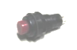 | 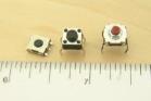 |
| (Fig. 182) Push ON/OFF switch | (Fig. 183) Micro-switches |
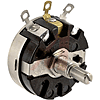
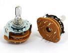
(3) Selector
The above switches can control only one circuit group. If a number of circuit groups are to be controlled at the same time, another type of switch is needed. This kind of switch is called selector. It can be manually controlled (selector) or electronically controlled (multiplexer).
Manual selectors are called (n Pole n Throw) selectors, e.g. 1P2T selector:
| Symbol: | 1P2T selector |
A practical example: Connect a circuit of motor control to three options of power supply: (i) OFF circuit, (ii) a 9V dry cell and (iii) a 9V DC converter
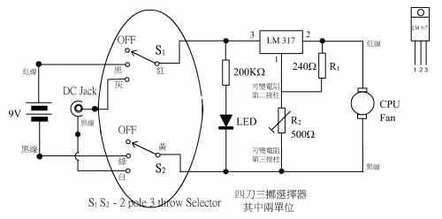 |  | ||
| A 2P3T selector can be used to carry out the required job (Fig. 184). | (Fig. 184) A 2P3T selector | ||
A special kind of electronic selector called multiplexer will be mentioned in Topic 9.2.
m. Relay
Relay is a kind of electronic component for electrical control. When electric current, reaches a threshold requirement (input loop), the output loop is activated. It can be looked upon as an electrical switch. It is usually used in automatic control system. Normally employed in circuits requiring a small current to control a load with larger current consumption. Frequently used in automatic conditioning, safety applications and circuit interchange situations.
| Symbol: |  |
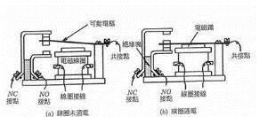

Types of relay
(1) Electromagnetic relay (Fig. 185): Electromagnetic force generated by the primary circuit current and an iron core coil triggers a secondary ON/OFF switch for activating the secondary circuit.
 |  |
| (Fig. 185) 2P3T electromagnetic relay | (Fig. 186) 2P3T solid state relay |
(2) Solid state relay (Fig. 186): All electronic components without mechanical parts to carry out similar function.
(3) Temperature relay: A relay which is swiched on when attained a certain fixed temperature.
One simple example: Using sound to activate a lamp bulb for illumination.
 |  |
(Fig. 187) A simple sound activated lamp illumination
Clapping sound is picked up by a microphone. The audio signal is amplified and activates the relay which in turn switch on the power supply (Fig. 187). However, the circuit is too simple, the activated bulb will flash once and back to the non-illuminated state when the clapping sound is gone. A desired situation is for the bulb to turn ON after the clapping sound and stays as it is. A second clapping sound will turn the bulb OFF, like the design shown in (Fig. 188).
|  |
(Fig. 188) An improved schematic circuit that will perform clap ON and clap OFF operation
Although the design is not too demanding, the improvement needs a quite complicated circuit. One commercial DIY kit for this purpose uses a 555 timer and a D flip flop IC 7474. For details of circuit, operation principle and required components, please refer to the following website: http://www.theorycircuit.com/clap-switch-circuit-with-relay/
Project (6) Use a breadboard to complete the circuit of a DIY sound activated switch kit and control the ON/OFF state of a light bulb.
Material: Breadboard. DIY sound activated switch kit, 9V battery, light bulb, connecting wires, crocodile clips
If one does not want to use a manual switch to control a circuit, relay is a good alternative.
Project (7) Solder a DIY sound activated swich kit onto a universal circuit board and control the ON/OFF state of a light bulb.
Material: Universal circuit board, DIY sound activated switch kit, 9V battery, light bulb, connecting wires, soldering iron and accessories.
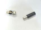
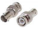
n. Plug and socket
| Symbol of plug and socket: |